Introduction
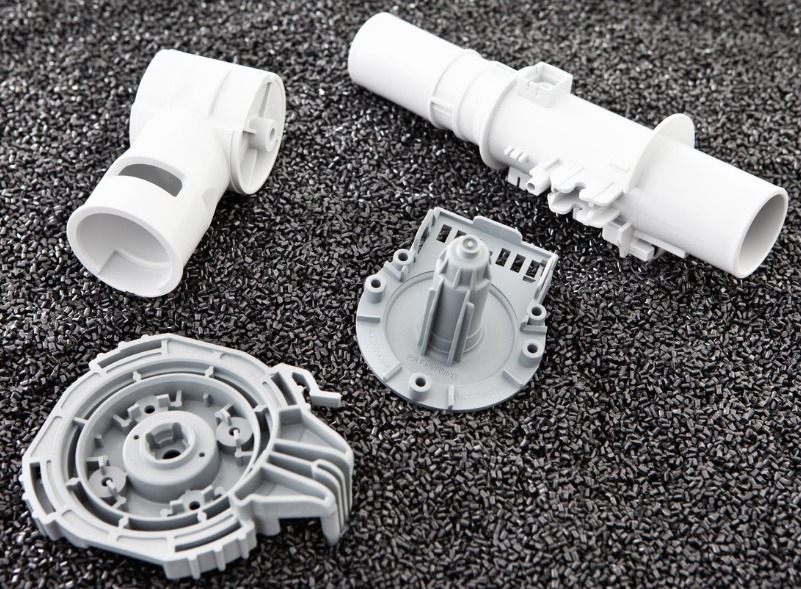
Behind every plastic part made by injection moulding lies a complex tool—the mould. This mould is not a single piece. It is an assembly of many components working together to shape, cool, and eject each part.
Understanding injection moulding tool parts is essential for anyone involved in manufacturing. Whether you are designing a new product, troubleshooting production issues, or sourcing moulds, knowing what each part does helps you make better decisions.
This guide breaks down the core components of an injection mould. You will learn what each part does, how they work together, and what to consider when selecting or designing them. By the end, you will understand the building blocks that create the plastic products you use every day.
What Are the Core Components?
Every injection mould contains several essential components. Each serves a specific function.
Core and Cavity
The core and cavity are the heart of the mould. They form the shape of the plastic part.
| Component | Function | Example |
|---|---|---|
| Cavity | Forms the outer shape of the part | In a bottle mould, the cavity shapes the outer walls, neck, and body |
| Core | Forms the internal features | In a bottle mould, the core creates the hollow interior space |
The core and cavity are typically made from hardened steel (like P20 or H13) to withstand high pressures and temperatures. For prototype or low-volume moulds, aluminum may be used.
Surface finish matters. A polished cavity produces glossy parts. A textured cavity creates matte or patterned surfaces—common on consumer electronics and automotive interiors.
Gating System
The gating system delivers molten plastic from the machine nozzle to the cavity.
Gate – The entry point where plastic enters the cavity. Gate type affects part quality and appearance.
| Gate Type | Best For | Trade-off |
|---|---|---|
| Pin gate | Small, precision parts | Minimal vestige; requires three-plate mould |
| Edge gate | Flat parts, general use | Visible mark; easy to machine |
| Submarine gate | Automatic degating | Self-trimming; higher mould complexity |
| Fan gate | Large, thin parts | Even flow; leaves mark |
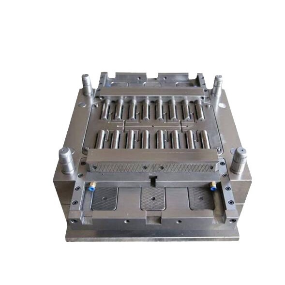
Runner – The channel that connects the sprue to the gate. In multi-cavity moulds, runners distribute plastic evenly to each cavity.
A well-designed runner system minimizes pressure drop. For a mould producing eight identical caps, the runner lengths to each cavity should be balanced so all cavities fill at the same time.
Ejection System
Once the part cools, it must be removed from the mould. The ejection system does this.
Ejector pins – Metal rods that push the part out. They are placed in areas where they will not damage the part—typically on thick sections or non-cosmetic surfaces.
For a flat plate, ejector pins might be placed around the perimeter or at evenly spaced points across the surface.
Ejector plate – Holds the ejector pins and moves them forward when activated by the machine.
Return pins – Push the ejector plate back after ejection, ensuring it is in the correct position before the next cycle.
Some applications use alternative ejection methods:
- Air ejection – Uses compressed air to blow the part off. Common for large, flat parts like automotive dashboards.
- Stripper plates – A plate that pushes the part off uniformly. Used for parts with deep undercuts or thin walls.
What Are the Supporting Components?
Beyond the core components, several other parts keep the mould functioning.
Cooling System
The cooling system removes heat from the plastic so it solidifies. Cooling channels are drilled into the mould plates. Coolant (usually water) circulates through them.
Key elements:
- Cooling channels – Strategically placed near the cavity for efficient heat transfer
- Baffles and bubblers – Direct coolant into hard-to-reach areas
- O-rings and seals – Prevent leaks
Cooling accounts for 50–80% of cycle time. A well-designed cooling system reduces cycle time and prevents warpage.
Guiding Components
Mould halves must align precisely every cycle.
Guide pins and guide bushes – Ensure the moving half aligns with the fixed half when the mould closes. Misalignment causes flash and premature wear.
Interlocks – Provide additional alignment for large or complex moulds.
Sprue and Locating Ring
Sprue – The tapered channel that connects the machine nozzle to the runner system. It is the first point of entry for molten plastic.
Locating ring – Centers the mould on the injection machine’s platen. Ensures the nozzle aligns with the sprue bushing.
What Are Standard vs. Non-Standard Parts?
Injection moulding tool parts fall into two categories: standard and non-standard.
| Aspect | Standard Parts | Non-Standard Parts |
|---|---|---|
| Design | Follow industry standards; available in catalogs | Custom-designed for specific projects |
| Examples | Ejector pins (2mm, 3mm, 5mm diameters), guide pins, sprue bushings | Custom cores with complex shapes; specialized cooling components |
| Manufacturing | Mass-produced; cost-effective | Custom-machined; higher cost; longer lead time |
| Tolerances | ±0.05mm typical | Can be as tight as ±0.01mm |
| Application | General-purpose moulds | High-precision or specialized applications |
When to use standard parts:
- General-purpose moulds
- Prototype or low-volume tools
- Applications where cost is a primary driver
When to use non-standard parts:
- Complex part geometries
- Tight tolerance requirements (±0.01mm or better)
- Medical devices, aerospace, or precision electronics
- Unique cooling or ejection requirements
A case example: A manufacturer producing medical connectors needed a core with a complex internal geometry. Standard cores could not achieve the required shape. A non-standard core was custom-machined using EDM, with tolerances held to ±0.005mm. The part passed all functional tests.
What Are Specialized Parts for Unique Applications?
Different industries require specialized mould components.
Precision Electronic Components
For small electronic connectors and micro-components:
- Cores and cavities require tolerances in the micron range (±0.005mm)
- Hot runner systems with multiple pin-point gates maintain consistent flow
- Vacuum venting removes air from tiny cavities
A misalignment of even 0.01mm can cause electrical contact failure. Mould components for these applications are often made from stainless steel or hardened tool steel with specialized coatings to prevent wear.
Automotive Interior Components
Large automotive parts like dashboards and door panels have unique requirements:
- Large cavities – Often single-cavity moulds due to part size
- Air ejection systems – Replace ejector pins to avoid surface marks on visible areas
- Conformal cooling – Channels that follow the part shape for uniform cooling
- Slide systems – For undercuts and complex geometry
A case example: An automotive supplier producing dashboard panels switched from pin ejection to air ejection. Surface defects dropped by 90%, and the rejection rate fell from 8% to under 1%.
Medical Device Moulds
Medical moulds require:
- Corrosion-resistant steels (stainless) to prevent contamination
- Polished surfaces – Mirror finishes prevent bacteria adhesion
- Full traceability – Each mould component is documented
- Cleanroom compatibility – Components designed to minimize particle generation
What Materials Are Used for Tool Parts?
Material selection affects mould life, part quality, and cost.
| Material | Properties | Typical Applications |
|---|---|---|
| P20 Steel | Pre-hardened; good machinability; moderate wear resistance | General-purpose moulds; 100,000–500,000 cycles |
| H13 Steel | Heat-treated; excellent toughness; high wear resistance | High-volume production; 1M+ cycles |
| Stainless Steel (420, 17-4) | Corrosion-resistant; can be hardened | Medical moulds; food-contact applications |
| Aluminum | Lightweight; excellent thermal conductivity; lower cost | Prototype moulds; low-volume production (10,000–50,000 cycles) |
| Copper Alloys | Superior thermal conductivity | Cooling components; bubblers; baffles |
How Do You Choose?
- Production volume – High volume demands hardened steel; low volume can use aluminum
- Material being moulded – Abrasive materials (glass-filled) require harder steels
- Corrosion risk – PVC and other materials release corrosive gases; stainless steel is recommended
- Cooling requirements – Copper alloys improve heat transfer in critical areas
How Are Tool Parts Manufactured?
Different manufacturing techniques produce mould components.
CNC Machining
Computer-controlled mills and lathes cut components from solid metal. Used for:
- Core and cavity roughing and finishing
- Guide pin holes
- Ejector pin holes
EDM (Electrical Discharge Machining)
Uses electrical sparks to erode metal. Essential for:
- Sharp internal corners
- Complex geometries
- Fine details
- Hardened materials that are difficult to machine
A case example: A mould for a connector required sharp 90-degree internal corners. CNC could not achieve the geometry. EDM created the corners precisely, with no radius.
Grinding and Polishing
- Surface grinding – Creates flat, parallel surfaces
- Cylindrical grinding – Produces precise pins and bushings
- Hand polishing – Achieves mirror finishes on cavity surfaces
How Do You Maintain Tool Parts?
Regular maintenance extends mould life and prevents defects.
Preventive Maintenance Schedule
| Frequency | Task |
|---|---|
| Daily | Clean parting lines; apply lubricant to moving parts; check coolant flow |
| Weekly | Inspect ejector pins for wear; clean vent channels; check guide pins for galling |
| Monthly | Measure critical dimensions; inspect cooling channels for scale; check gate condition |
| Per production run | Clean and inspect; apply rust preventive if mould will sit idle |
Common Wear Issues
| Component | Wear Pattern | Solution |
|---|---|---|
| Ejector pins | Galling; bending; breakage | Replace; improve lubrication |
| Guide pins/bushes | Wear; misalignment | Replace; check alignment |
| Gates | Enlargement; erosion | Replace gate inserts; adjust processing |
| Cooling channels | Scale buildup; corrosion | Chemical flush; use treated water |
| Parting lines | Damage from flash | Polish or weld and re-machine |
Conclusion
Injection moulding tool parts work together as a system to create plastic parts. The core and cavity define the shape. The gating system controls flow. The ejection system removes the finished part. Cooling channels manage heat. Guiding components ensure alignment.
Understanding these components helps you:
- Design parts that are easier to mould
- Troubleshoot production issues
- Communicate effectively with mould makers
- Make informed decisions about standard vs. custom components
Whether you are building a simple single-cavity mould or a complex multi-cavity system for medical devices, the fundamentals remain the same. Quality components, properly maintained, deliver consistent parts over hundreds of thousands or millions of cycles.
Frequently Asked Questions (FAQ)
How do I choose the right material for injection moulding tool parts?
Consider production volume, material being moulded, and corrosion risk. For high-volume production (1M+ cycles), use hardened tool steel like H13. For moderate volumes (100,000–500,000 cycles), P20 steel is a good balance of cost and durability. For prototypes or low volumes, aluminum reduces cost and lead time. For abrasive or corrosive materials, consider stainless steel or coated components.
What is the typical lifespan of injection moulding tool parts?
Lifespan varies widely. In normal conditions with moderate production (50,000–100,000 cycles per year), standard steel components can last 200,000–300,000 cycles. High-volume production (500,000+ cycles per year) or harsh conditions may reduce lifespan to 100,000–150,000 cycles. Proper maintenance—cleaning, lubrication, and cooling—extends life significantly.
Can injection moulding tool parts be repaired?
Yes, many components can be repaired. Minor surface damage can be polished out. Cracks in cores or cavities can be welded (TIG welding for steel) if the damage is not extensive. Worn ejector pins or guide pins are typically replaced rather than repaired. For non-standard parts, the cost of repair must be weighed against replacement cost. Complex repairs may require EDM to restore geometry.
What is the difference between standard and non-standard tool parts?
Standard parts follow industry specifications and are available from catalog suppliers. Examples include ejector pins, guide pins, and sprue bushings. They are mass-produced, cost-effective, and suitable for general-purpose moulds. Non-standard parts are custom-designed and manufactured for specific projects. They are used for complex geometries, tight tolerances, or unique cooling and ejection requirements. Non-standard parts cost more and have longer lead times but enable specialized applications.
How do I prevent common ejection problems?
Part sticking often results from insufficient draft angle or poor surface finish. Add draft (1–3 degrees) and polish the cavity. Ejector pin marks indicate pins are too small, poorly placed, or applying uneven force. Distribute pins evenly and increase pin size or number. Part deformation during ejection suggests cooling is incomplete or ejection force is too high. Extend cooling time or reduce ejection speed.
Contact Yigu Technology for Custom Manufacturing
At Yigu Technology, we specialize in custom injection moulding tool parts for demanding applications. Our expertise spans material selection, precision manufacturing, and quality control.
Our capabilities include:
- Custom cores and cavities with complex geometries
- Precision gating systems for consistent flow
- Specialized cooling components including conformal cooling
- High-quality ejector systems for clean part removal
- Non-standard components with tolerances as tight as ±0.01mm
We work with clients across medical, automotive, electronics, and consumer goods industries. Every component is manufactured to your specifications and inspected using CMM and other precision measurement tools.
Contact us today to discuss your injection moulding tool part requirements. Let our experience help you build better moulds that run longer and produce higher-quality parts.