Introduction
Injection molding relies on precise mechanisms to produce quality parts. One of the most critical components in any mold is the ejector rod. It pushes finished parts out of the mold cavity after cooling.
But ejector rods themselves must be manufactured with high precision. They need exact dimensions, smooth surfaces, and consistent material properties. Ejector rod injection molding is the specialized process that creates these essential components.
This guide explains how the process works, what components are involved, and why precision matters for your molds and finished products.
What Is an Ejector Rod?
An ejector rod is a cylindrical component within an injection mold. It transfers force from the machine’s ejection system to the ejector pins, which push the finished part out of the cavity.
Ejector rods must withstand repeated mechanical stress. They need high strength, dimensional accuracy, and surface smoothness to function reliably over thousands or millions of cycles.
Typical ejector rods have:
- A cylindrical body with precise diameter
- Specific length based on mold design
- Possible features like grooves or threaded ends
- Hardened surfaces for wear resistance
How Does Ejector Rod Injection Molding Work?
The process follows the same basic principles as standard injection molding but with specialized considerations for these precision components.
Step 1: Material Preparation
Plastic pellets undergo drying before processing. Hygroscopic materials like nylon absorb moisture from the air. If moisture remains, it turns to steam during injection, creating voids or bubbles in the finished rod.
Drying parameters vary by material:
- Nylon: 80°C to 100°C for 2 to 4 hours
- ABS: 80°C to 85°C for 2 to 3 hours
- Polycarbonate: 120°C for 2 to 4 hours
Additives may also be mixed at this stage. Colorants provide identification colors. UV stabilizers protect rods exposed to sunlight. Flame retardants add fire resistance when required.
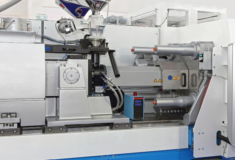
Step 2: Heating and Melting
The dried material enters the barrel. A rotating screw conveys it forward. Heat from barrel heaters and friction from screw rotation melt the plastic.
Temperature is controlled in zones:
- Rear zone: Lower temperature, around 150°C to 180°C for standard plastics
- Front zone: Higher temperature, up to 200°C to 250°C near the nozzle
Proper temperature control is essential. Too low, and the plastic does not melt fully, causing short shots. Too high, and the material degrades, losing mechanical properties.
Step 3: Injection
The screw moves forward under high pressure. It forces molten plastic through the nozzle into the mold cavity.
Injection pressure typically ranges from 50 to 200 MPa. Higher pressure fills complex cavities. Too much pressure causes flash—excess plastic leaking between mold surfaces.
Injection speed also matters. Fast speeds fill the cavity quickly, preventing premature cooling. But speeds that are too fast can trap air, creating voids. Slow speeds extend cycle time and may cause uneven filling.
Step 4: Cooling and Solidification
Cooling channels circulate water or other media through the mold. They extract heat from the molten plastic.
Cooling time depends on:
- Rod thickness
- Material properties
- Mold cooling efficiency
A thin rod in fast-cooling plastic like polystyrene may cool in 5 to 10 seconds. A thick rod in engineering plastic like PEEK may take several minutes.
Cooling must be uniform. Uneven cooling creates internal stresses that lead to warping or cracking.
Step 5: Ejection
After solidification, the mold opens. The ejection system activates.
Ejector pins contact the finished rod. Hydraulic or mechanical force pushes the pins forward, ejecting the rod from the cavity.
Ejection force must be carefully controlled. Too little force leaves the part stuck. Too much force can bend or break the rod.
The table below summarizes the process steps:
| Step | Key Parameters | Common Issues |
|---|---|---|
| Material Preparation | Drying temperature, time | Moisture causing voids |
| Heating | Zone temperatures, screw speed | Incomplete melting, degradation |
| Injection | Pressure, speed | Short shots, flash, trapped air |
| Cooling | Time, cooling medium uniformity | Warping, internal stress |
| Ejection | Force, pin placement | Damage, incomplete ejection |
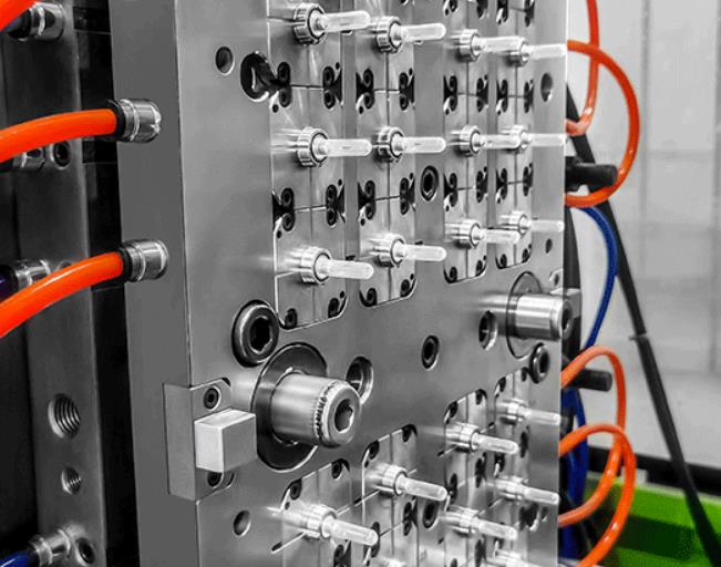
What Are the Key Mold Components?
Cavity and Core
The cavity forms the outer shape of the ejector rod. It is machined to exact specifications, including diameter, length, and any surface features like threads or grooves.
The core forms the inner portion. For a solid rod, the core is simple. For rods with internal channels or features, the core becomes more complex.
Slides
Slides create undercuts or side features. They move laterally within the mold during the cycle.
If an ejector rod has a groove along its side, a slide forms that groove during injection. After solidification, the slide retracts, allowing the rod to eject cleanly.
Injection System Components
The screw conveys, melts, and mixes the plastic. Its design—pitch, diameter, and compression ratio—affects how well the material melts.
The barrel houses the screw. Heating bands create temperature zones along its length. The inner surface must be smooth to minimize friction.
The nozzle connects the barrel to the mold. Its orifice controls flow rate. It must seal tightly against the mold’s sprue bushing to prevent leaks.
Ejection Mechanism
Ejector pins are slender rods that contact the finished part. They are placed strategically to push evenly without marking the rod’s surface.
Ejector rods (the mechanism components, not the product) transfer force from the machine to the ejector pins. They are made of high-strength steel to withstand repeated forces.
What Tolerances Can Be Achieved?
Ejector rods require high precision. The mold cavity determines final dimensions. Any imperfection transfers to the finished product.
Modern injection molding achieves tolerances as tight as ±0.01 mm for ejector rods. This level of precision is essential in industries like automotive and electronics, where mold components must fit and function reliably over millions of cycles.
Surface finish also matters. Smooth surfaces reduce friction during ejection and extend mold life. Post-processing like polishing can improve finish further.
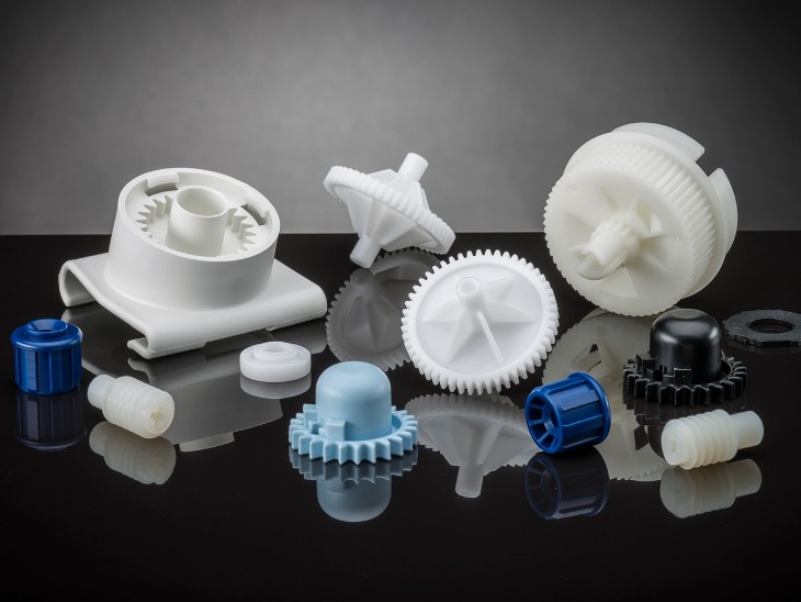
What Materials Are Used?
| Material | Properties | Applications |
|---|---|---|
| Nylon (PA) | High strength, wear resistance, slightly hygroscopic | General-purpose ejector rods |
| PEEK | Excellent heat resistance, chemical stability | High-temperature applications |
| Polycarbonate (PC) | Impact resistance, dimensional stability | Precision applications requiring toughness |
| Steel (for metal injection molding) | Maximum strength, wear resistance | High-cycle molds, heavy-duty applications |
For metal ejector rods, Metal Injection Molding (MIM) allows complex shapes with material properties similar to wrought steel.
What Defects Can Occur and How to Prevent Them?
Short Shots
Cause: Insufficient injection pressure or speed, low melt temperature.
Prevention: Increase pressure or temperature. Verify material is fully melted.
Flash
Cause: Excessive injection pressure, mold damage, or improper clamping.
Prevention: Reduce pressure. Check mold surfaces for wear. Verify clamping force.
Voids or Bubbles
Cause: Trapped air or moisture in the material.
Prevention: Dry material thoroughly. Optimize injection speed to allow air to escape. Add vents to mold.
Warping
Cause: Uneven cooling or internal stresses.
Prevention: Design uniform cooling channels. Adjust cooling time. Balance wall thickness.
Surface Marks from Ejection
Cause: Ejector pins placed improperly or excessive ejection force.
Prevention: Position pins evenly. Polish pin surfaces. Calibrate ejection force.
What Does a Real-World Example Look Like?
A manufacturer of high-volume automotive connectors needed ejector rods for their molds. The rods required a diameter tolerance of ±0.01 mm and a surface finish better than 0.4 μm Ra. The previous supplier delivered rods with inconsistent dimensions, causing ejector pins to bind and production delays.
The solution involved a redesigned mold cavity with optimized cooling channels. Material selection focused on a glass-filled nylon for strength and wear resistance. Process parameters were dialed in with precise temperature control and a staged injection profile.
The result was ejector rods that maintained tolerance across production runs. Ejector pin binding stopped. Mold downtime decreased by 25% , and part quality improved.
Conclusion
Ejector rod injection molding produces the precision components that make injection molds function reliably. The process requires careful control of material preparation, temperature, pressure, cooling, and ejection.
Key components—cavity, core, slides, injection system, and ejection mechanism—must work together seamlessly. Tolerances as tight as ±0.01 mm are achievable with proper mold design and process control.
When ejector rods are manufactured correctly, molds run longer with fewer interruptions. Finished parts eject cleanly without damage. Production efficiency increases, and quality improves.
FAQ
What is the difference between ejector rods and ejector pins?
Ejector rods are larger-diameter components that transfer force from the machine’s ejection system to the ejector pins. Ejector pins are smaller, slender rods that contact the finished part directly and push it out of the mold cavity. Both work together in the ejection mechanism.
What materials are best for ejector rods?
Steel is used for high-cycle molds requiring maximum strength and wear resistance. Engineering plastics like nylon and PEEK work for lower-cycle applications or where corrosion resistance is needed. Material choice depends on cycle count, operating environment, and cost requirements.
How do you prevent ejector rod surface damage during ejection?
Ensure ejector pins are evenly distributed around the rod’s contact surface. Polish pin faces to a smooth finish. Calibrate ejection force to the minimum required to eject the part. Use proper draft angles in the mold design.
What tolerances can ejector rod injection molding achieve?
With precision mold design and controlled process parameters, tolerances as tight as ±0.01 mm are achievable. This level of precision ensures consistent performance and long mold life.
Why is material drying important for ejector rod quality?
Hygroscopic plastics absorb moisture from the air. During injection, this moisture turns to steam. The steam creates voids and bubbles in the finished rod, weakening its structure and compromising dimensional accuracy. Proper drying eliminates this risk.
Contact Yigu Technology for Custom Manufacturing
At Yigu Technology, we specialize in precision injection molding for critical components like ejector rods. Our engineers understand the demands of high-cycle molds and precision applications.
We offer a wide range of materials, including engineering plastics and metal injection molding options. Our quality control system ensures every component meets your specifications.
Whether you need standard ejector rods or custom designs with complex features, we deliver reliability and precision.
Contact Yigu Technology today to discuss your ejector rod or custom manufacturing project.