Introduction
UHMWPE (ultra-high molecular weight polyethylene) offers an exceptional combination of properties: extremely low friction, outstanding wear resistance, and remarkable impact strength. These characteristics make it ideal for medical implants, food processing equipment, and industrial wear parts. But the same properties that make UHMWPE valuable also create machining challenges. Its low coefficient of friction causes parts to slip in fixtures. Its toughness leads to deformation under cutting forces. And its low thermal conductivity traps heat, causing melting and chip welding. This guide addresses these challenges directly, providing proven strategies for CNC machining UHMWPE reliably and accurately.
What Makes UHMWPE Different?
A High-Performance Polymer
UHMWPE is a polyethylene with an extremely high molecular weight—typically 3.5 to 7.5 million g/mol. This gives it properties that set it apart from other plastics.
Key properties:
| Property | UHMWPE | PTFE | HDPE |
|---|---|---|---|
| Coefficient of friction (dry) | 0.05–0.15 | 0.04 | 0.2–0.3 |
| Wear resistance | Excellent | Very Good | Good |
| Impact strength | Excellent | Good | Very Good |
| Density (g/cm³) | 0.93–0.94 | 2.1–2.3 | 0.94–0.96 |
| Biocompatibility | Yes (ISO 10993) | Yes | Limited |
Low friction: UHMWPE’s coefficient of friction is 0.05–0.15—comparable to PTFE. This makes it ideal for bearings, guides, and sliding surfaces. But it also means the material slips easily in standard fixtures.
High wear resistance: UHMWPE outperforms most plastics and even some metals in abrasive environments. This makes it suitable for conveyor wear strips, scraper blades, and marine applications.
Impact resistance: UHMWPE absorbs energy without fracturing. It is used in bulletproof vests and protective equipment.
Chemical resistance: It resists most acids, alkalis, and organic solvents—essential for food processing and chemical handling.
What Machining Challenges Does UHMWPE Present?
Slippage in Fixtures
UHMWPE’s low friction is a design advantage but a machining problem. The material slides in standard clamps and vises. Even vacuum fixtures can fail if not properly designed.
Deformation Under Cutting Forces
UHMWPE is tough and elastic. Cutting forces push the material away rather than shearing it cleanly. This leads to:
- Burrs and rough edges
- Dimensional inaccuracy
- Tearing on exit
Heat Buildup and Melting
UHMWPE has low thermal conductivity. Heat generated at the cutting edge does not dissipate quickly. It accumulates, causing:
- Localized melting
- Chip welding to the tool
- Surface smearing
Post-Machining Dimensional Shift
UHMWPE exhibits creep—slow deformation under sustained stress. Residual stresses from machining can cause parts to change dimensions over hours or days. Final inspection too soon can yield inaccurate measurements.
How Do You Machine UHMWPE Effectively?
Milling Techniques
Milling is the most common operation for UHMWPE. Success depends on tool selection and parameter control.
Tool selection:
- Sharp carbide end mills with polished flutes
- 2-flute or 3-flute designs for chip evacuation
- High rake angles (10–15°) to reduce cutting forces
Parameters:
- Spindle speed: 3,000–6,000 RPM
- Feed rate: 0.15–0.3 mm/tooth
- Depth of cut: 0.5–2 mm for roughing; 0.1–0.2 mm for finishing
- Climb milling for clean cuts on thicker sections
- Conventional milling for thin sections to prevent pull
Key technique: Use multiple shallow passes rather than deep cuts. This reduces deformation and heat buildup.
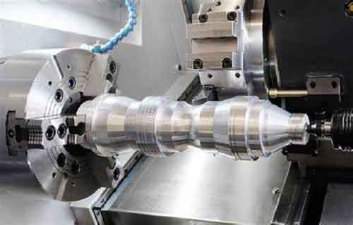
Turning Techniques
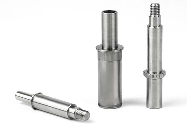
Turning produces cylindrical parts like bushings, rollers, and medical implant components.
Tool selection:
- Carbide inserts with positive rake angle (10–15°)
- Sharp, polished cutting edges
- Fine-grain carbide for longer tool life
Parameters:
- Spindle speed: 1,500–3,000 RPM
- Feed rate: 0.1–0.2 mm/rev
- Depth of cut: 0.5–2 mm roughing; 0.1–0.3 mm finishing
Workholding:
- Soft jaws machined to part contour
- Textured chuck surfaces to improve grip
- Light clamping pressure—UHMWPE deforms under force
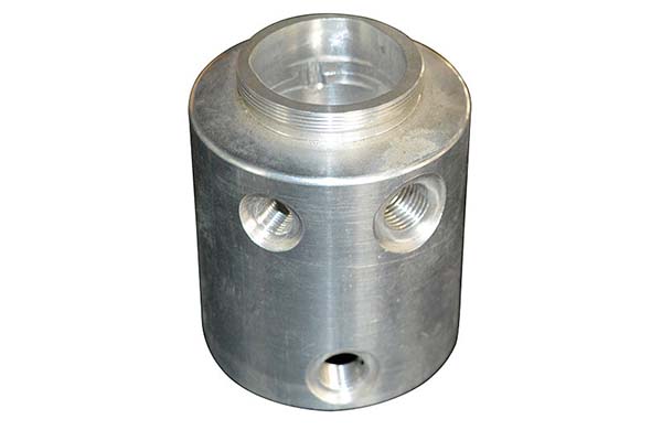
Drilling and Tapping
Drilling UHMWPE requires care to prevent tearing and heat buildup.
Drilling:
- 118° point angle drills with polished flutes
- Peck drilling (1–2 mm per peck) to clear chips
- Speed: 1,500–3,000 RPM
- Feed: 0.05–0.15 mm/rev
Tapping:
- Spiral-flute taps for through holes
- Spiral-point taps for blind holes
- Speed: 500–1,000 RPM
- Use cutting fluid (minimal) to reduce friction
What Tools and Fixtures Work Best?
Tool Selection
| Tool Type | Recommendation | Why |
|---|---|---|
| End mills | 2-flute carbide, polished flutes | Chip evacuation, sharp edges |
| Inserts | Positive rake (10–15°) | Reduced cutting forces |
| Drills | 118° point, polished flutes | Clean entry, reduced heat |
| Taps | Spiral-flute | Chip evacuation, clean threads |
Tool coatings: Uncoated carbide works well. TiN or TiAlN coatings are not necessary and may increase friction. Sharpness is more important than coating.
Fixturing for Low Friction
Standard clamps fail. UHMWPE slides out. Effective fixturing requires:
Vacuum fixtures:
- High-force vacuum tables: ≥ -90 kPa
- Multiple zones for different part sizes
- Soft rubber seals to prevent air leaks
Soft jaws:
- Machined to match part geometry
- Textured surfaces (grooves or knurling) to increase friction
- Light clamping pressure—just enough to hold
Workholding tips:
- Use sacrificial backing to support thin sections
- Minimize overhang to reduce deflection
- Consider double-sided tape for thin sheets
Coolant Strategy
UHMWPE does not require liquid coolant. In fact, prolonged exposure to liquid can cause slight swelling.
Recommended:
- Compressed air directed at the cutting zone
- Mist coolant (2–5% concentration) for deep cuts or high-volume production
Avoid:
- Flood coolant—can cause swelling
- Oil-based coolants—absorbed by the material
How Do You Control Heat and Deformation?
Heat Management
Heat is the enemy in UHMWPE machining. It causes melting, smearing, and chip welding.
Heat prevention:
- Use sharp tools—dull tools generate friction heat
- Maintain adequate feed rates—too slow causes rubbing
- Climb mill for cleaner cuts with less heat
- Air blast for continuous cooling
- Multiple shallow passes rather than deep cuts
Deformation Prevention
UHMWPE deflects under cutting forces. This causes dimensional inaccuracy and burrs.
Strategies:
- Positive rake tools reduce cutting forces
- Light finishing passes (0.1–0.2 mm depth)
- Conventional milling for thin sections (prevents pull)
- Sacrificial backing for thin parts
What Quality Control Measures Matter?
Dimensional Inspection
UHMWPE relaxes after machining. Stresses from cutting cause gradual dimensional change.
Best practice:
- Allow 24 hours for stress relaxation before final inspection
- Inspect in temperature-controlled environment (20–22°C)
- Use CMMs for complex geometries
- Achievable tolerances: ±0.03–0.05 mm standard; ±0.01–0.02 mm for precision parts
Case example: A medical implant manufacturer found that parts measured immediately after machining passed inspection, but 48 hours later they had grown by 0.02 mm. Implementing a 24-hour stabilization period before final measurement eliminated this issue.
Surface Finish
| Application | Target Ra (μm) |
|---|---|
| General industrial | 1.6–3.2 |
| Food processing | 1.6–3.2 |
| Medical implants | <0.8 |
| Bearing surfaces | <0.8 |
Achieving better finish:
- Sharp tools with polished flutes
- Reduced feed rate on finishing passes (0.05–0.1 mm/tooth)
- Light finishing pass (0.05–0.1 mm depth)
- PCD tools for high-volume precision work
Non-Destructive Testing
For critical applications:
- Visual inspection under magnification (20–50×): Detects surface defects, burrs, and melt marks
- Ultrasonic testing: Identifies subsurface voids in thick sections
- Hardness testing: Shore D (60–70) verifies material consistency—variations can indicate inconsistent molecular weight
Where Is Machined UHMWPE Used?
Medical Implants
UHMWPE is the material of choice for hip and knee replacement components. Its low friction and wear resistance allow smooth articulation with minimal particle generation. Biocompatibility (ISO 10993) ensures it does not react with human tissue.
Machining requirements:
- Cleanroom processing (Class 8)
- Surface finish Ra <0.8 μm to minimize wear
- Tight tolerances for proper fit
- Sterilization compatibility
Food Processing Equipment
Conveyor guides, star wheels, and chute liners use UHMWPE for its:
- Chemical resistance (cleaning agents)
- Non-stick properties
- FDA compliance for food contact
- Low friction (reduces product damage)
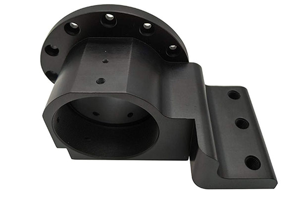
Industrial Wear Parts
Bearings, bushings, and scraper blades benefit from UHMWPE’s:
- High wear resistance
- Low friction (reduces energy consumption)
- Impact resistance (absorbs shock)
Case example: A mining operation replaced steel wear plates with UHMWPE. The new parts lasted 3× longer and reduced conveyor power consumption by 15%.
Marine Applications
Dock fenders, boat hull liners, and propeller shaft sleeves resist saltwater corrosion and reduce friction, extending equipment life in harsh marine environments.
Automotive Parts
Door handles, gearshift components, and fuel system seals use UHMWPE’s impact resistance and chemical tolerance to withstand under-hood conditions.
A Real-World UHMWPE Machining Success
A medical device manufacturer producing hip replacement liners faced quality issues:
- Surface finish inconsistent (Ra 1.2–2.5 μm)
- Parts slipping in fixtures during machining
- Dimensional variation across batches
After process changes:
- Switched to vacuum fixture with textured surface (≥ -90 kPa)
- Reduced spindle speed from 8,000 RPM to 4,500 RPM
- Used compressed air cooling instead of flood coolant
- Implemented 24-hour stabilization before final inspection
- Added light finishing pass (0.05 mm depth) with PCD tool
Results:
- Surface finish improved to Ra 0.6–0.8 μm
- Zero slippage during machining
- Dimensional variation reduced by 70%
- Scrap rate dropped from 12% to 3%
- Customer approved for production
Conclusion
CNC machining UHMWPE requires understanding and respecting the material’s unique properties. Its low friction demands specialized fixturing—vacuum tables and textured soft jaws. Its toughness requires sharp tools, positive rake angles, and multiple shallow passes. Its low thermal conductivity makes air cooling essential to prevent melting and chip welding. And its tendency to creep after machining requires patience—allow 24 hours for stress relaxation before final inspection. When these factors are addressed, UHMWPE machines into precision components that deliver exceptional wear resistance, low friction, and impact strength across medical, food processing, industrial, and marine applications.
FAQs
Why does UHMWPE slip during machining, and how can I prevent it?
UHMWPE’s low coefficient of friction (0.05–0.15) causes slippage even with standard fixtures. Prevention requires high-force vacuum fixtures (≥ -90 kPa), soft jaws with textured surfaces, and minimal depth of cut (≤1 mm) to reduce lateral forces. For turning operations, use soft jaws machined to the part contour and light clamping pressure.
How do I avoid melting and chip welding when machining UHMWPE?
Melting occurs from heat buildup caused by low thermal conductivity. To avoid it: use sharp tools with positive rake angles, maintain spindle speeds of 4,000–6,000 RPM with adequate feed rates (0.2–0.3 mm/tooth), and use compressed air for cooling. Multiple shallow passes generate less heat than deep cuts. Avoid flood coolant, which can cause swelling.
What surface roughness is achievable in UHMWPE, and how can I improve it for medical applications?
Standard machining achieves Ra 1.6–3.2 μm. For medical implants requiring Ra <0.8 μm, use PCD (polycrystalline diamond) tools, increase spindle speed to 6,000–8,000 RPM on finishing passes, take a light finishing pass (0.05–0.1 mm depth), and ensure tools are sharp with polished flutes. Post-machining, parts may require inspection only after 24-hour stabilization.
What tolerances can I expect when machining UHMWPE?
Standard tolerances of ±0.03–0.05 mm are achievable with proper setup. Precision applications—such as medical implants—can achieve ±0.01–0.02 mm. Critical to success: use rigid setups, sharp tools, multiple shallow passes, and allow 24 hours for stress relaxation before final inspection. Measure in a temperature-controlled environment.
Do I need coolant when machining UHMWPE?
Coolant is generally not required. Compressed air is preferred for cooling and chip evacuation. Air prevents heat buildup without the risk of swelling from liquid exposure. For deep cuts or high-volume production, minimal mist coolant (2–5% concentration) can be used, but avoid flood coolant and oil-based coolants, which UHMWPE can absorb.
Contact Yigu Technology for Custom Manufacturing
At Yigu Technology, we specialize in CNC machining UHMWPE for medical, food processing, industrial, and marine applications. Our engineering team understands UHMWPE’s unique challenges—low friction, deformation, heat sensitivity—and selects the right tools, fixtures, and parameters for each project. We use high-force vacuum fixtures to prevent slippage, sharp carbide and PCD tools for clean cuts, and compressed air cooling to manage heat. Quality control includes CMM inspection, surface finish verification, and, for medical applications, Class 8 cleanroom processing. Contact us to discuss your UHMWPE machining project.