Introduction
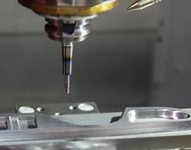
You are staring at a block of material. It needs to become a precision component. But which material should you choose? Pick wrong, and your tools wear out in minutes. Pick right, and the job runs smoothly from start to finish.
The choice of milling material is one of the most critical decisions in machining. It affects everything: tool life, cycle time, surface finish, and ultimately the cost of your part. In aerospace, medical, and automotive manufacturing, the wrong material choice can mean failed inspections, scrapped parts, and missed deadlines.
At Yigu Technology, we machine a wide range of materials every day. This guide walks you through the key considerations—from basic material properties to advanced processing strategies—so you can make informed decisions for your next project.
What Are the Basic Material Properties?
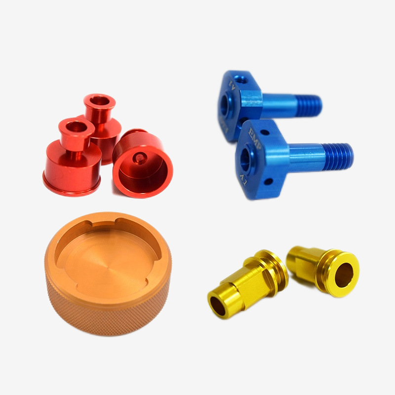
Metals: The Workhorses of Manufacturing
Metals remain the most common milling materials. Each type has distinct characteristics that determine how it machines.
| Material | Core Features | Typical Applications | Machinability (1–5) |
|---|---|---|---|
| Aluminum alloy | Lightweight, good thermal conductivity, low hardness | Aircraft parts, automotive housings, electronic enclosures | 4.5 |
| Stainless steel | Corrosion resistance, high strength | Medical devices, chemical equipment, food processing | 3.0 |
| Titanium alloy | High strength-to-weight, heat resistance, biocompatible | Turbine blades, orthopedic implants, aerospace structures | 2.0 |
| Tool steel | High hardness, wear resistance | Molds, dies, cutting tools | 1.5–2.5 |
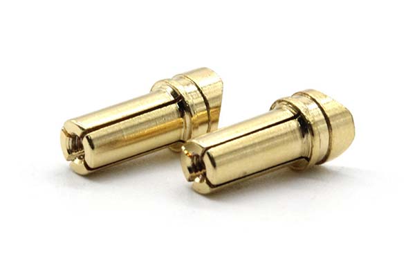
| Brass/Copper | Good conductivity, machinable | Electrical connectors, plumbing fittings | 4.0 |
Real-World Example:
An aerospace parts factory was machining titanium alloy blades. Titanium has high strength and low thermal conductivity—heat stays in the cutting zone. Using standard parameters, tool wear reached 20% per hour. After optimizing the process (cutting speed reduced, coolant increased), wear dropped to under 5%.
The lesson: material properties dictate the approach. Titanium is not aluminum. Treat it differently, or pay the price.
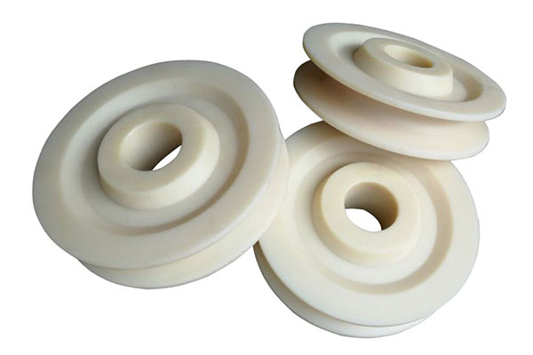
Non-Metals: Emerging Applications
Non-metallic materials are increasingly common in high-performance applications.
| Material | Core Features | Applications | Machining Considerations |
|---|---|---|---|
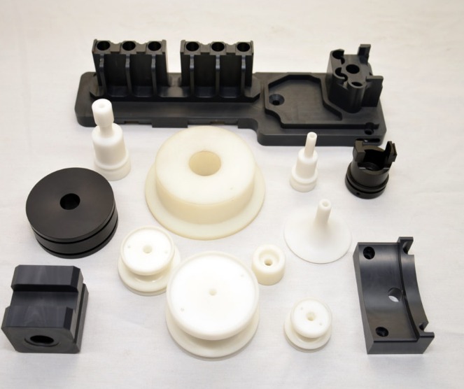
| Engineering plastics (PEEK, nylon) | Wear-resistant, insulating, lightweight | Electronic housings, medical devices, gears | Temperature control; risk of melting |
| Composites (carbon fiber) | High specific strength, lightweight | Aerospace structures, racing cars | Fiber cracking; abrasive to tools |
| Wood | Natural, aesthetic | Furniture, architectural models | Grain direction; burr control |
PEEK (Polyether Ether Ketone) deserves special mention. It withstands 260°C continuous use and resists almost all chemicals. But it machines differently than metals—sharp tools and careful heat management are essential.
Hardness, Strength, and Machinability
Three properties determine how a material behaves during milling:
Hardness: Resistance to indentation. Higher hardness means more cutting force and faster tool wear.
Strength: Resistance to deformation. High-strength materials can spring away from the tool, causing vibration.
Machinability rating: An industry-standard score (1–5, with 5 being easiest to machine) based on cutting force, tool wear rate, and achievable surface finish.
A material with machinability rating 1 (like Inconel) requires specialized tools and careful parameter selection. A rating 5 material (like free-cutting brass) can be machined quickly with standard tools.
Heat Treatment State Changes Everything
The same material can machine very differently depending on its heat treatment.
| State | Effect | Milling Impact |
|---|---|---|
| Annealed | Soft, reduced hardness | Easier cutting; longer tool life |
| Quenched | Hard, increased strength | Requires harder tools; slower speeds |
| Tempered | Balanced hardness/toughness | Moderate machinability |
Real-World Example:
A mold factory needed to machine Cr12MoV mold steel. Direct milling in the hardened state (HRC 60+) caused tool chipping and slow progress. After annealing to HRC 25–30, machining speed increased 3 times, and tool life improved dramatically. The parts were then heat-treated to final hardness after machining.
The principle: machine in the softest state that still allows final properties to be achieved.
How to Optimize Milling Parameters?
Cutting Speed and Feed Rate
These two parameters control the "rhythm" of machining. Get them wrong, and you face overheating, poor finish, or broken tools.
Cutting speed (Vc): The linear speed of the cutting edge relative to the material (m/min). Too high = tool overheating. Too low = inefficient.
Feed rate (fz): The distance the tool moves per tooth per revolution (mm/tooth). Too high = burrs and poor finish. Too low = rubbing and heat.
Practical Reference Table:
| Material | Cutting Speed (m/min) | Feed Rate (mm/tooth) | Recommended Tool |
|---|---|---|---|
| Aluminum 6061 | 300–500 | 0.2–0.5 | Carbide, uncoated |
| Stainless 304 | 100–150 | 0.1–0.3 | Coated carbide |
| Titanium TC4 | 50–80 | 0.05–0.2 | Ceramic or coated carbide |
| PEEK plastic | 200–300 | 0.1–0.2 | Sharp carbide |
| Carbon fiber | 100–200 | 0.05–0.1 | Diamond-coated |
These are starting points. Actual parameters depend on machine rigidity, tool condition, and coolant.
Milling Force and Tool Load
Milling force is the force exerted by the tool on the material. Excessive force causes deflection, vibration, and tool failure.
Strategies to manage tool load:
- Layered milling: Split depth of cut into multiple passes. Instead of cutting 5 mm deep in one pass, take five 1 mm passes. Tool load decreases significantly.
- Optimize toolpaths: Avoid plunging straight down. Use spiral or ramped entries to engage the tool gradually.
- Reduce radial engagement: Taking a lighter cut width reduces force without sacrificing feed rate.
Coolant and Lubrication Strategy
Coolant does more than cool. It lubricates the cutting edge and evacuates chips.
| Strategy | Best For | Benefits |
|---|---|---|
| Wet milling | Stainless steel, titanium, superalloys | Reduces tool wear by 30%+; better surface finish |
| Dry milling | Aluminum, wood, plastics | Lower cost; environmentally friendly; no cleanup |
| MQL (minimum quantity lubrication) | Most materials | Small amount of oil in air blast; balance of cooling and cost |
Real-World Example:
An auto parts factory milling aluminum cylinder blocks switched from wet to dry milling. With cutting speed at 400 m/min, they achieved Ra 0.8 μm surface finish—well within specifications. Eliminating coolant reduced operating costs and eliminated disposal concerns.
High-Speed Milling
High-speed milling (HSM) uses cutting speeds 2–5 times higher than conventional. It can dramatically increase productivity, but requires:
- Material suitability: Best for aluminum, plastics, and soft steels
- Equipment: Rigid machines with spindles ≥10,000 RPM
- Parameter adjustment: Reduce feed rate to 50–70% of conventional; increase speed
When done right, HSM can reduce cycle times by 50% or more while improving surface finish.
How to Select the Right Cutting Tools?
Tool Materials
The tool material must match the workpiece material.
| Tool Material | Properties | Best For | Cost |
|---|---|---|---|
| High-speed steel (HSS) | Tough, forgiving | Wood, mild steel, machinability rating ≥4 | Low |
| Carbide | Hard, wear-resistant | Stainless steel, aluminum, general purpose | Moderate |
| Coated carbide | Heat-resistant, lubricious | Difficult materials, high-speed applications | Moderate–High |
| Ceramic | Extremely hard, heat-resistant | Titanium, superalloys, hardened steel | High |
| CBN/PCD | Ultra-hard | Hard turning, abrasive composites | Very high |
Rule of thumb: Tool hardness should exceed material hardness by at least 3 HRC. For titanium and superalloys, ceramic or CBN tools are often necessary.
Tool Geometry
The shape of the tool affects chip flow, surface finish, and tool life.
| Geometry Element | Impact | Guidelines |
|---|---|---|
| Flute count | Roughing: fewer flutes (2–3) for chip clearance; finishing: more flutes (4–6) for better surface | Match to operation |
| Helix angle | 30–45° for aluminum (reduces sticking); 45–60° for stainless (longer cutting edge) | Higher angle = smoother cut |
| Coatings | TiN: general purpose; TiAlN: high-temperature; DLC: friction reduction for plastics | Match to material |
Special Tools for Special Needs
| Tool Type | Purpose | Example Application |
|---|---|---|
| Roughing mill | Aggressive material removal | Mold steel roughing |
| Finishing mill | Surface quality | Medical device finishing |
| Profile mill | Complex contours | Aerospace blade profiling |
| Ball end mill | Curved surfaces | Mold cavities, 3D contours |
Tool Wear and Life Management
Tool wear is inevitable. Managing it is essential for cost control.
Signs of tool wear:
- Deteriorating surface finish (Ra > specified limit)
- Dimensional drift
- Increased cutting noise or vibration
- Visible edge chipping or flank wear >0.2 mm
Extending tool life:
- Use tool life management systems to track cutting time
- Replace tools based on predicted life, not failure
- Match tool to material—the right coating can double life
Real-World Example:
A mold factory machining Cr12MoV steel switched from uncoated carbide to TiAlN-coated carbide. Tool life increased from 50 parts per tool to 150 parts per tool. Per-part tool cost dropped by 20%.
Tool-Material Matching Principles
Three principles guide tool selection:
- Hardness matching: Tool hardness must exceed material hardness
- Performance complementarity: Hydrophobic coatings for sticky materials (aluminum); tough tools for high-strength materials (titanium)
- Efficiency priority: High-wear-resistance tools for production runs; general-purpose tools for prototypes
How Do Industry Applications Affect Material Choice?
Aerospace Materials: Extreme Demands
Aerospace components face extreme temperatures, stresses, and reliability requirements.
Common materials:
- Superalloys (Inconel 718, Waspaloy): High-temperature strength, machinability rating 1.5
- Titanium alloys (Ti6Al4V): High strength-to-weight, corrosion resistance
- Carbon fiber composites: Lightweight, high stiffness
Machining challenges:
- Superalloys work-harden rapidly
- Titanium retains heat, accelerating tool wear
- Carbon fiber is abrasive and prone to delamination
Solution strategies:
- For superalloys: ceramic tools + wet milling, cutting speed 80–100 m/min, feed 0.1 mm/z
- For titanium: coated carbide, low speed (50–80 m/min), high-pressure coolant
- For carbon fiber: diamond-coated tools, climb milling to prevent fiber pull-out
Data point: An aerospace factory implementing optimized parameters for superalloy blades achieved 40% higher efficiency and surface finish of Ra 0.4 μm.
Die Steel Molding: Precision Meets Toughness
Mold steels like Cr12MoV and H13 require both precision and durability.
Requirements:
- Dimensional tolerance: ±0.005 mm
- Surface finish: Ra ≤ 0.8 μm
- Hardness after heat treatment: 50–60 HRC
Process flow:
- Anneal to reduce hardness (HRC 25–30)
- Rough mill to near-net shape
- Heat treat to final hardness
- Finish mill with high-speed machining
Real-World Example:
A mold shop processing H13 steel adopted a "rough milling → aging → finishing" sequence. Scrap rates dropped from 5% to 1%. The aging step between rough and finish machining relieved residual stresses that caused warping.
Medical Device Materials: Safety First
Medical implants and instruments have unique requirements beyond mechanical properties.
Common materials:
- Cobalt-chromium alloys: High wear resistance, biocompatible
- Titanium: Biocompatible, non-magnetic
- Stainless steel 316L: Corrosion-resistant, cost-effective
Special considerations:
- Biocompatibility: No contamination; tools must be sterile or sterilizable
- Precision: Implant tolerances often ±0.003 mm
- Surface finish: Ra ≤ 0.2 μm for implant surfaces that contact tissue
Machining approach:
- Cobalt-chromium: ceramic tools + dry milling (coolant can contaminate)
- Titanium: coated carbide, sharp edges to avoid work hardening
- Inspection: 100% CMM verification; no sampling
Strategies for Difficult-to-Machine Materials
Materials with machinability rating ≤2 require special strategies.
| Strategy | Application | Benefit |
|---|---|---|
| Pre-treatment annealing | Tool steel, superalloys | Reduces hardness by 20–30% |
| Specialized tools | PCD, CBN for abrasive/hard materials | 5–10x longer tool life |
| Cryogenic machining | Titanium, Inconel | Liquid nitrogen cooling reduces heat; extends tool life |
| High-pressure coolant | Stainless, titanium | 1000+ psi coolant breaks chips; improves finish |
New Material Trends
The manufacturing landscape is evolving. New materials bring new challenges.
Lightweight materials: Carbon fiber, magnesium alloy, aluminum-lithium alloys. Demand is growing—aerospace lightweight material milling demand is expected to grow 35% by 2025 (China Machinery Industry Federation).
Functional materials: Shape memory alloys (Nitinol), ceramic matrix composites. These require specialized milling techniques still under development.
Hybrid materials: Metal-polymer composites, graded materials. Machining requires understanding of both constituents.
How to Make the Right Choice?
A Decision Framework
When selecting a milling material, consider:
- Application requirements: What must the part withstand? Temperature? Load? Environment?
- Machinability: Can you machine it efficiently with your equipment?
- Cost: Material cost + machining cost + tooling cost + scrap risk
- Availability: Is the material available in the required form and quantity?
- Post-processing: Does it need heat treatment? Coating? Surface finishing?
Common Mistakes to Avoid
| Mistake | Consequence | Prevention |
|---|---|---|
| Ignoring heat treatment state | Excessive tool wear | Specify annealed for machining |
| Using wrong tool material | Premature failure | Match tool hardness to material |
| Inconsistent coolant | Poor surface finish | Define strategy per material |
| Overlooking material certificates | Failed inspections | Require certifications upfront |
Conclusion
Choosing the right milling material is about understanding the relationship between material properties, machining parameters, and tool selection. A material that machines easily may not have the properties your application requires. A high-performance material may demand specialized tools and slower speeds.
The key is to start with the application requirements, then work backward. What strength? What hardness? What corrosion resistance? Once those are defined, you can evaluate machinability and develop a process that balances quality, efficiency, and cost.
At Yigu Technology, we apply this approach every day. We match the right materials to the right processes, ensuring that the parts we deliver meet specifications and arrive on time.
FAQ
How do I solve tool sticking problems when milling aluminum?
Use TiAlN or DLC-coated tools. Increase cutting speed to 300–500 m/min. Use dry milling or kerosene as coolant. Reduce feed rate to 0.2–0.3 mm/z. The key is preventing aluminum from welding to the cutting edge—sharp tools and proper lubrication are essential.
What tools are best for difficult materials like titanium alloys?
Ceramic tools or PCD tools with TiAlN coating are preferred. Use low speed (50–80 m/min), small feed (0.05–0.2 mm/z), and layered milling (shallow depth of cut). High-pressure coolant helps break chips and evacuate heat. Avoid stopping the tool in the cut—dwell causes work hardening.
How do I choose between dry and wet milling?
- Dry milling: Best for easy-to-cut materials (aluminum, wood, plastics). Lower cost, environmentally friendly. Ensure adequate chip evacuation.
- Wet milling: Required for difficult materials (stainless steel, titanium, superalloys). Cooling reduces tool wear by 30%+ and improves surface finish.
The choice also depends on machine capability—some machines are not designed for wet operation.
How can I tell when a tool needs replacement?
Replace tools when you observe:
- Surface roughness exceeds specification (e.g., Ra > 1.6 μm)
- Dimensional tolerance drift
- Visible edge chipping or flank wear >0.2 mm
- Increased cutting noise or vibration
Waiting until tools fail completely risks scrapped parts and machine damage.
What are the core process considerations for die steel milling?
- Start annealed: Machine in the soft state (HRC 25–30)
- Rough mill to near-net shape
- Heat treat to final hardness
- Finish mill with high-speed machining (150–200 m/min)
- Use 4–6 flute finishing mills for best surface finish
The intermediate heat treatment relieves stresses that would otherwise cause warping during finishing.
Contact Yigu Technology for Custom Manufacturing
At Yigu Technology, we specialize in precision milling across a wide range of materials. From aluminum and stainless steel to titanium, PEEK, and carbon fiber, we have the expertise to select the right material and process for your application.
Our capabilities include 3-axis and 5-axis milling, high-speed machining, and multi-process manufacturing. We serve the aerospace, medical, automotive, and industrial sectors with components that meet the most demanding specifications.
We do not just machine materials. We help you choose them wisely.
Contact us today to discuss your milling project.