Introduction
Transparent plastics are everywhere. They form the lenses in your glasses, the screens on your smartphone, the headlights on your car, and the covers on medical devices. Clarity is not just aesthetic—it is functional. A hazy lens distorts vision. A scratched display screen is unusable. A void in a medical fluid container compromises safety.
Molding transparent plastics is demanding. Even minor defects—micro-voids, flow lines, surface scratches—ruin optical clarity. Color variations that are invisible in opaque parts stand out in clear ones. Process parameters must be balanced precisely to prevent warpage while maintaining high gloss.
This guide covers the properties of transparent plastics, the molding process, mold design, quality control, and applications to help you produce crystal-clear, high-quality parts.
What Are the Key Properties of Transparent Plastics?
Transparent plastics transmit light with minimal scattering. But different materials offer different balances of clarity, strength, heat resistance, and durability.
Optical Clarity
Light transmission rates vary by material:
| Material | Light Transmission |
|---|---|
| PMMA (Acrylic) | 92 – 93% |
| PC (Polycarbonate) | 89 – 90% |
| COC (Cyclic Olefin Copolymer) | Up to 94% |
Higher transmission rates are essential for precision optical components—lenses, display covers, optical connectors.
Refractive Index
Refractive index affects how light bends through the material:
| Material | Refractive Index |
|---|---|
| PMMA | 1.49 |
| COC | 1.53 |
| PC | 1.59 |
This is critical for lens design. The wrong refractive index causes distortion.
UV Resistance
PMMA resists UV yellowing better than PC, making it ideal for outdoor applications—skylights, signage. PC requires UV stabilizers for long-term outdoor use.
Scratch Resistance
PMMA is more scratch-resistant than PC. Both benefit from hard coatings—diamond-like carbon or silicone-based—for added protection.
Impact Resistance
| Material | Notched Izod Impact Strength (kJ/m²) |
|---|---|
| PMMA | 2 – 4 |
| PC | 60 – 80 |
PC far exceeds PMMA in impact resistance, making it better for safety glasses, automotive lenses, and protective covers.
Thermal Stability
| Material | Continuous Use Temperature |
|---|---|
| PMMA | 80°C |
| PC | 120°C |
| COC | 100 – 160°C |
COC handles higher temperatures, suitable for applications requiring sterilization or heat exposure.
Chemical Resistance
COC offers the strongest chemical resistance—resists oils and solvents. PMMA is vulnerable to alcohols.
Dimensional Stability
Coefficient of thermal expansion (CTE):
| Material | CTE (ppm/°C) |
|---|---|
| COC | 60 – 70 |
| PC | 70 – 80 |
Lower CTE means better dimensional stability—critical for precision parts like optical connectors.
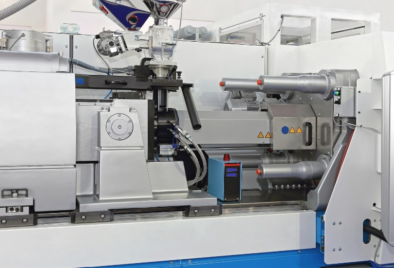
How Do You Injection Mold Transparent Plastics?
Drying Requirements
Moisture causes cloudiness. Hygroscopic materials must be dried thoroughly:
| Material | Drying Conditions | Target Moisture |
|---|---|---|
| PC | 120°C for 4 – 6 hours | <0.02% |
| PMMA | 80°C for 2 – 4 hours | <0.02% |
| COC | 100°C for 3 – 5 hours | <0.02% |
Melt Temperature
| Material | Range |
|---|---|
| PMMA | 210 – 240°C |
| COC | 230 – 270°C |
| PC | 280 – 300°C |
Exceeding these ranges causes degradation—yellowing or haze.
Injection Pressure
80 to 140 MPa. Higher pressures needed for complex geometries to ensure complete filling without voids.
Injection Speed
Moderate to high—50 to 80 mm/s —to minimize flow marks. Too fast causes shear heating and degradation.
Cooling Time
| Material | Cooling Time |
|---|---|
| PMMA | 15 – 25 seconds |
| PC | 20 – 30 seconds |
Proper cooling prevents internal stress that causes birefringence—optical distortion.
Cycle Time
30 to 60 seconds. High-gloss processing may require slower cooling to maintain surface smoothness.
Runner and Gate Design
Avoid sharp corners that trap air. Edge gates work for flat parts. Submarine gates reduce visible gate marks on lenses.
Process Optimization
- If flow lines appear, slow injection speed
- If sink marks appear, increase hold pressure
- Use incremental adjustments—small changes prevent overcorrection
The table below summarizes key parameters:
| Parameter | PMMA | PC | COC |
|---|---|---|---|
| Drying | 80°C, 2–4h | 120°C, 4–6h | 100°C, 3–5h |
| Melt temperature | 210–240°C | 280–300°C | 230–270°C |
| Injection pressure | 80–140 MPa | 80–140 MPa | 80–140 MPa |
| Injection speed | 50–80 mm/s | 50–80 mm/s | 50–80 mm/s |
| Cooling time | 15–25 s | 20–30 s | 15–25 s |
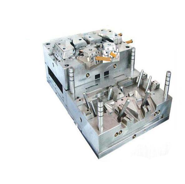
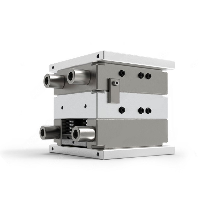
How Should Molds Be Designed for Transparent Plastics?
Mold Materials
- P20 steel with diamond polish: Surface finish Ra <0.02 μm. Suitable for general use.
- Stainless steel: Prevents corrosion in high-moisture environments.
Mold Flow Analysis
Simulates flow to identify air traps or weld lines. Weld lines appear as haze in transparent parts—must be avoided.
Cooling Channel Layout
Uniform channels 8 to 12 mm from cavity prevent uneven cooling and warpage. Water temperature:
- PC: 60 – 70°C
- PMMA: 50 – 60°C
Venting
Strict venting prevents air bubbles. Vent depth: 0.01 to 0.02 mm at flow ends.
Draft Angles
0.5° to 1°. Reduces friction during ejection, protecting the high-gloss mold surface and preventing scratches.
Ejector Pin Design
Use large, flat pins or stripper plates to distribute force evenly. Avoids marks that mar clarity.
Hot Runner Systems
Valve gates reduce weld lines and gate marks—critical for lenses.
Surface Finish
Non-negotiable. Even microscopic scratches on the mold transfer to the part. Regular polishing required.
What Defects Occur and How to Prevent Them?
| Defect | Cause | Solution |
|---|---|---|
| Haze/cloudiness | Moisture or degradation | Improve drying; lower melt temperature |
| Flow lines | Slow injection speed or uneven flow | Increase speed; optimize gate location |
| Voids | Trapped air or insufficient packing | Add vents; increase hold pressure |
| Warpage | Uneven cooling | Balance cooling channels; adjust cooling time |
| Scratches | Poor mold release or rough handling | Polish mold; use release agents sparingly |
| Birefringence | Internal stress | Optimize cooling; adjust packing pressure |
Quality Control Methods
Visual inspection: LED lights detect haze.
Light transmission measurement: Spectrophotometers target >90% for clear parts.
Birefringence check: Polariscopes detect optical distortion—critical for lenses and displays.
Statistical Process Control (SPC): Monitor melt temperature (±5°C), pressure (±10 MPa). Flag deviations before defects occur.
Dimensional accuracy: CMMs with ±0.005 mm precision—critical for optical components.
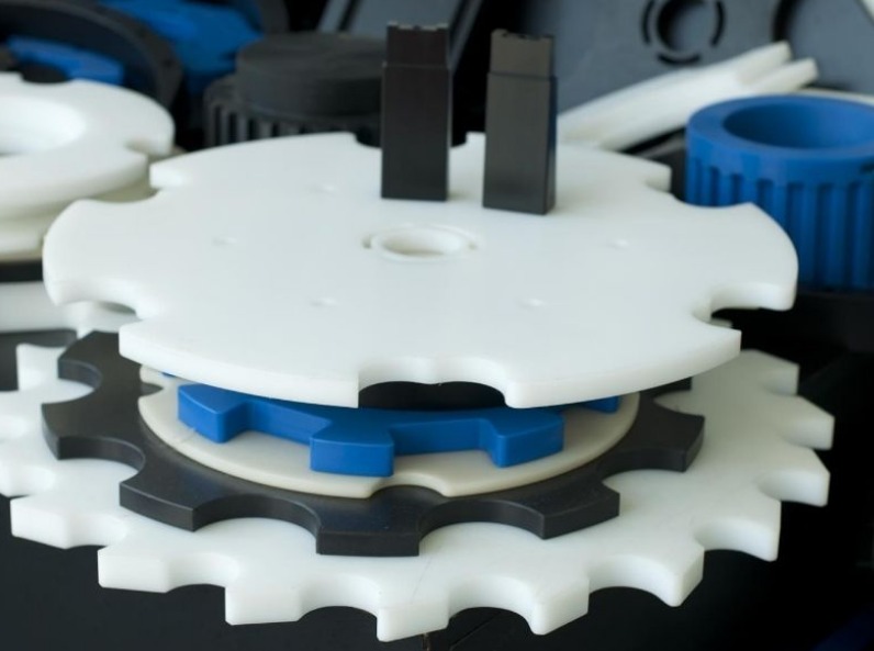
Where Are Transparent Plastics Used?
Optical Components
| Component | Material | Property Used |
|---|---|---|
| Camera lenses | COC | Precision, clarity |
| Eyeglass lenses | PMMA | Scratch resistance |
| Fiber optic connectors | PC | Impact resistance, dimensional stability |
Lighting Fixtures
| Component | Material | Property Used |
|---|---|---|
| LED covers | PC | Heat resistance |
| Streetlight diffusers | PMMA | UV stability |
Automotive Lenses
| Component | Material | Property Used |
|---|---|---|
| Headlights | PC with hard coating | Impact resistance, clarity |
| Instrument clusters | PMMA | Clarity, scratch resistance |
Medical Devices
| Component | Material | Property Used |
|---|---|---|
| IV fluid containers | COC | Chemical resistance |
| Surgical light covers | PC | Impact safety, clarity |
Consumer Electronics
| Component | Material | Property Used |
|---|---|---|
| Smartphone screens | PC with scratch coating | Impact resistance, clarity |
| Smartwatch displays | PMMA | Cost-effectiveness, clarity |
Design for Manufacturing Tips
- Uniform wall thickness (2–3 mm) prevents sink marks
- Rounded corners reduce stress concentrations that cause haze
What Post-Processing Options Exist?
Surface Treatments
Hard coating: Diamond-like carbon or silicone-based coatings boost scratch resistance on PC and PMMA. Common for eyewear and displays.
Painting and Coating
Clear, UV-stable coatings applied in dust-free environments. Particles cause visible defects.
Adhesive Bonding
Optically clear adhesives (OCA) for lenses and displays. No visible glue lines.
Ultrasonic Welding
Works for PC and PMMA. Creates strong bonds without affecting clarity. Ideal for medical device assemblies.
Machining and Trimming
Sharp carbide tools at low speeds prevent chipping. Critical for precision lenses.
Assembly Tolerances
±0.01 mm for optical components to ensure proper alignment.
Finishing Standards
ISO 10110 for optical parts specifies allowable defects—scratches, bubbles.
What Does a Real-World Example Look Like?
A manufacturer of automotive headlights needed PC lenses with:
- Light transmission >89%
- No haze or flow lines
- Impact resistance to withstand road debris
- UV stability for outdoor exposure
The solution:
- Material: UV-stabilized PC
- Drying: 120°C for 5 hours, moisture <0.02%
- Mold: P20 steel with diamond polish (Ra 0.01 μm); hot runner with valve gates
- Parameters: Melt temperature 290°C, injection pressure 120 MPa, injection speed 70 mm/s, cooling time 25 seconds
- Post-processing: Hard coating for scratch resistance
The result: lenses with 90% light transmission, no visible defects, and passed impact testing. Production volume: 500,000 units annually with defect rate under 2%.
Conclusion
Injection molding transparent plastics requires meticulous control of materials, process, and mold design.
Material properties:
- Light transmission: 89–94% (PC, PMMA, COC)
- Refractive index: 1.49–1.59 (critical for lens design)
- Impact resistance: PC far exceeds PMMA (60–80 kJ/m² vs. 2–4 kJ/m²)
- Thermal stability: COC handles 100–160°C; PC 120°C; PMMA 80°C
Process parameters:
- Drying: PC 120°C/4–6h, PMMA 80°C/2–4h, COC 100°C/3–5h—all to <0.02% moisture
- Melt temperature: 210–300°C depending on material
- Injection pressure: 80–140 MPa; speed 50–80 mm/s
- Cooling time: 15–30 seconds
Mold design:
- Mirror finish (Ra <0.02 μm) on P20 or stainless steel
- Uniform cooling channels 8–12 mm from cavity
- Vent depth 0.01–0.02 mm
- Draft angles 0.5–1°
- Hot runners with valve gates reduce weld lines
Quality control:
- Light transmission >90% for clear parts
- Birefringence checked with polariscopes
- CMM dimensional accuracy ±0.005 mm
- SPC monitoring (±5°C, ±10 MPa)
Applications range from optical components to automotive lenses, medical devices, and consumer electronics.
When executed correctly, transparent plastic injection molding delivers crystal-clear, high-quality parts that meet demanding optical and functional requirements.
FAQ
Which transparent plastic is best for outdoor applications?
PMMA (acrylic) is ideal for outdoor use due to superior UV resistance—it resists yellowing better than PC. For impact-resistant outdoor parts like safety barriers, use UV-stabilized PC. For long-term outdoor exposure, ensure proper UV stabilizers are added to PC.
How can I improve scratch resistance in transparent plastics?
Apply hard coatings—silicone dioxide or diamond-like carbon—significantly boost scratch resistance in PC and PMMA. COC has inherent scratch resistance, suitable for low-maintenance applications. For molded parts, ensure mold surface finish is mirror-like (Ra <0.02 μm) to prevent initial surface defects.
Can recycled transparent plastics be used for optical components?
Recycled transparent plastics often have reduced optical clarity and color consistency, making them unsuitable for lenses or displays. They work well for non-critical applications—packaging, decorative parts. For optical components, use virgin material with full traceability.
What causes haze in transparent plastic parts?
Haze is primarily caused by moisture in the material or thermal degradation. Moisture causes cloudiness when it turns to steam during molding. Degradation—excessive melt temperature or long residence time—causes yellowing and haze. Solutions: dry materials to <0.02% moisture; maintain melt temperature within recommended ranges; minimize residence time.
How do I prevent flow lines in transparent parts?
Flow lines are caused by slow injection speed or uneven flow. Increase injection speed (50–80 mm/s typical). Optimize gate location to ensure uniform filling. Use mold flow analysis to identify problem areas before tooling. Ensure melt temperature is within range to maintain flowability.
Contact Yigu Technology for Custom Manufacturing
At Yigu Technology , we specialize in transparent plastic injection molding. Our molds are polished to mirror finishes (Ra <0.02 μm). We use strict drying protocols—PC at 120°C for 5 hours, PMMA at 80°C for 3 hours—to achieve <0.02% moisture.
Our process control maintains melt temperature within ±5°C, injection pressure within ±10 MPa. Quality control includes light transmission testing, polariscope birefringence checks, and CMM dimensional verification.
From automotive lenses to medical device components, we deliver crystal-clear parts that meet the highest optical and functional standards.
Contact Yigu Technology today to discuss your transparent plastic injection molding project.