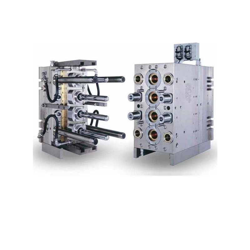
Introduction
In injection molding, air is the invisible enemy. When molten plastic rushes into a mold cavity, the air already inside must escape. If it cannot, defects follow.
Vent design is the practice of creating precise escape paths for this trapped air. It sounds simple, but poor venting causes some of the most common and costly molding defects: burns, short shots, and weak weld lines.
This guide explains vent design in plain terms. You will learn where vents go, how big they should be, and what types work best for different situations. You will also see real examples of how proper venting solves production problems. By the end, you will understand why venting is not an afterthought—it is a critical part of mold design.
Why Is Venting So Important?
When the injection molding machine pushes molten plastic into the mold, it displaces the air inside the cavity. That air needs a way out.
What Happens Without Proper Venting?
| Problem | Cause | Consequence |
|---|---|---|
| Air traps | Air cannot escape; gets surrounded by plastic | Voids, bubbles, weak spots |
| Dieseling (burns) | Trapped air compresses and heats up | Charred plastic; black streaks or burns |
| Short shots | Air pressure blocks plastic flow | Incomplete parts |
| Weld lines | Air disrupts melt fronts from fusing | Weak seams; visible lines |
| High clamp pressure | Compressed air pushes mold open | Flash; mold damage |
A Real-World Example
A manufacturer producing automotive interior trim pieces faced a recurring problem. Every run produced parts with small burn marks in a deep rib section. The defect rate was 12%.
The root cause? No venting at the bottom of the ribs. Air trapped in the deepest part of the cavity had no escape path. As the plastic filled, the air compressed and heated to over 300°C, scorching the plastic.
Adding 0.03 mm deep vents at the rib bases eliminated the burns. Defect rate dropped to 0.5%.
Where Should Vents Be Placed?
Vent location is the most critical decision in vent design. A perfectly sized vent in the wrong place does nothing.
What Is the Basic Rule?
Place vents at the end of the melt flow path. Air moves ahead of the plastic. The vent should be where the air naturally collects.
For a simple rectangular part with the gate on one end, vents go on the opposite end. For complex shapes, each flow path needs its own vent.
Where Are the High-Risk Areas?
- Deep ribs and bosses – Air gets trapped at the bottom
- Thin wall sections – Plastic freezes before air escapes
- Corners and sharp turns – Flow front changes direction; air can separate
- Last point to fill – Where melt fronts meet; weld line area
- Opposite side of gates – End of the primary flow path
A case example: A medical device housing had multiple internal bosses. The first mold had no venting at the boss bottoms. Every boss trapped air, causing burn marks. Adding vents at each boss location solved the problem. Cycle time increased by only 2 seconds, but scrap dropped from 18% to under 1%.
How Big Should Vents Be?
Vent size is a balance. Too small, and air cannot escape. Too large, and plastic leaks out—a defect called flash.
What Determines Vent Depth?
Vent depth is measured in thousandths of a millimeter. It is the most critical dimension. The correct depth depends on the material's viscosity at melt temperature.
| Material | Typical Vent Depth (mm) | Flash Risk If Deeper Than |
|---|---|---|
| PE (polyethylene) | 0.02 – 0.03 | 0.05 mm |
| PP (polypropylene) | 0.03 – 0.05 | 0.07 mm |
| ABS | 0.03 – 0.05 | 0.07 mm |
| PS (polystyrene) | 0.02 – 0.04 | 0.06 mm |
| PC (polycarbonate) | 0.05 – 0.08 | 0.10 mm |
| Nylon (PA) | 0.02 – 0.04 | 0.06 mm |
| PEEK | 0.03 – 0.07 | 0.10 mm |
What About Vent Width and Length?
Vent width can be much larger—typically 3 to 12 mm—because the plastic freezes quickly in the shallow depth and does not flow sideways.
Vent length (the shallow section) should be 1 to 2 mm. After that, a deeper relief channel (0.5 to 1.0 mm deep) allows air to escape freely without risk of flash.
A Practical Sizing Example
For an ABS part, a typical vent might be:
- Land depth: 0.04 mm
- Land length: 1.5 mm
- Relief depth: 0.5 mm
- Relief width: 6 mm
This vent lets air escape but stops plastic from flowing out.
What Types of Vents Are Available?
Different vent designs suit different locations and mold geometries.
Parting Line Vents
These are grooves cut into the mold surface at the parting line. They are the most common and easiest to machine.
Best for: Flat surfaces, edges, and general venting
Challenge: Must be positioned carefully to avoid flash on visible surfaces
A parting line vent typically extends 1–2 mm into the mold surface at the shallow depth, then opens into a wider relief channel.
Ejector Pin Vents
The small clearance between an ejector pin and its bushing can serve as a vent. This is useful when no parting line is nearby.
Best for: Deep cavities, rib ends, and areas away from parting line
Challenge: Venting area is limited by pin diameter
A 6 mm ejector pin with a clearance of 0.025 mm provides a small but effective vent. Multiple pins can be used together for more venting capacity.
Insert Vents
Small vent inserts are placed in specific areas where machining a vent into the main mold is difficult.
Best for: Complex geometry, retrofitting existing molds
Challenge: Higher cost; potential for insert movement
Vent Rings
Used around ejector pins or cores to provide 360-degree venting.
Best for: Round cores, tall bosses
Challenge: More complex to machine
How Are Vents Designed Step by Step?
A systematic approach to vent design prevents problems before production begins.
Step 1: Analyze the Part Geometry
Start by identifying all potential air trap locations. Walk the flow path in your mind or on screen.
- Mark the gate location
- Trace the flow front to the last fill points
- Identify deep features (ribs, bosses)
- Note any thin sections
- Consider where multiple flow fronts meet
Step 2: Run Mold Flow Analysis
Modern mold flow analysis software like Moldflow or Moldex3D simulates the filling process. It shows:
- Flow front progression – How plastic moves through the cavity
- Air trap locations – Areas where air gets surrounded
- Weld line positions – Where flow fronts meet
- Pressure distribution – Where venting is most needed
The software outputs color maps that clearly highlight problem areas. A simulation run costs a few hundred dollars but can prevent thousands in mold rework.
Step 3: Place Vents at Problem Areas
Based on the analysis, add vents at:
- All predicted air trap locations
- The end of every flow path
- Deep ribs and bosses
- Areas identified as last to fill
Step 4: Size Vents for the Material
Using the material-specific depth ranges, specify vent dimensions. When in doubt, start conservative. Vents can always be deepened later; they cannot be shallowed.
Step 5: Add Relief Channels
Each vent should open into a deeper relief channel (0.5–1.0 mm) that connects to the outside of the mold. This gives air a clear escape path.
How Does Material Choice Affect Vent Design?
Different plastics behave differently. Vents that work for one material may fail for another.
Low-Viscosity Materials
Examples: PE, PP, low-viscosity nylons
These materials flow easily and fill thin sections quickly. They also flash more easily. Use shallower vents—often at the lower end of the depth range.
Vent depth: 0.02–0.03 mm typically
High-Viscosity Materials
Examples: PC, PC/ABS blends, PEEK
These materials resist flow. They need deeper vents to allow air to escape before the plastic reaches the vent. They are less prone to flashing, so deeper vents are safe.
Vent depth: 0.05–0.08 mm typically
Filled Materials
Examples: Glass-filled nylon, mineral-filled PP
Fillers (glass fibers, minerals) make materials more abrasive and change flow behavior. Vents need to be sized for the base resin, but the abrasive nature means vents may wear over time.
Consideration: Use hardened steel in vent areas for long production runs.
Heat-Sensitive Materials
Examples: PVC, acetal (POM), some bio-plastics
These materials degrade if trapped air heats them. Venting is especially critical. Insufficient venting leads to brown streaks or burning.
Consideration: More venting capacity than the material's viscosity suggests.
What Are Common Venting Mistakes?
Even experienced mold makers can get venting wrong. Here are the most frequent issues.
Mistake 1: No Venting at Deep Ribs
Deep ribs are classic air traps. Without venting at the bottom, air compresses and burns the plastic.
Fix: Add vents at the bottom of every rib deeper than 5 mm.
Mistake 2: Vent Depth Too Shallow
Vents machined too shallow trap air. The operator may not notice until parts show burns or short shots.
Fix: Verify vent depths with precision gauges. Start with depths at the upper end of the range; test and adjust.
Mistake 3: Vent Depth Too Deep
Vents machined too deep cause flash. Once steel is cut too deep, the only fix is welding and re-machining.
Fix: Cut vents conservatively. Run test shots. Deepen incrementally until burns disappear.
Mistake 4: No Relief Channels
A shallow vent without a relief channel does not vent effectively. The air has nowhere to go.
Fix: Always machine a relief channel behind the shallow land.
Mistake 5: Venting Only at Parting Line
Relying only on parting line vents misses many problem areas. Ribs, bosses, and core pins need dedicated vents.
Fix: Use ejector pins, inserts, and custom vents at all potential trap locations.
How Do You Maintain Vents?
Vents work well when clean. Over time, they fill with plastic residue and require maintenance.
Regular Cleaning
During mold maintenance, clean vents with:
- Soft brass brushes
- Vent cleaning tools (thin blades)
- Ultrasonic cleaning for inserts
Do not use steel tools that could widen the vent depth.
Wear Monitoring
After hundreds of thousands of cycles, vents can wear or erode. Check depths periodically with a depth gauge or by test shots. When flash appears at a previously clean vent, it may be worn.
Restoration
Worn vents can be restored by:
- Re-machining the vent surface
- Replacing vent inserts
- Welding and re-cutting (for steel molds)
Conclusion
Injection molding vent design is a critical but often overlooked aspect of mold making. Proper venting prevents burns, short shots, and weak weld lines. It reduces scrap rates and cycle times. Poor venting leads to costly defects and production delays.
Effective vent design follows a clear process: analyze the part geometry, use mold flow analysis to predict air traps, place vents at the end of flow paths, size vents correctly for the material, and provide relief channels for air to escape.
Vent depth is the most critical dimension. It must match the material's viscosity—shallower for low-viscosity materials like PE and PP, deeper for high-viscosity materials like PC and PEEK.
Vents are not a one-time consideration. They require maintenance and occasional restoration over the mold's life. When designed and maintained correctly, they enable consistent, high-quality production.
Frequently Asked Questions (FAQ)
What is the most common mistake in injection molding vent design?
The most common mistake is improper vent location. Vents placed in the middle of the flow path rather than at the end of it fail to release trapped air. This causes burns, voids, and short shots. Always place vents where air naturally collects—at the end of flow paths, deep ribs, and last-to-fill areas.
How can I tell if my vent design is working?
Inspect parts for signs of trapped air. A well-vented mold produces parts with smooth surfaces, no burn marks, and complete filling. If you see burns, short shots, or visible air traps, venting is insufficient. For internal defects, use mold flow analysis to compare actual results with simulation. Consistent shot-to-shot quality also indicates effective venting.
Can vent design affect production cycle time?
Yes. Poor venting increases cycle time. Trapped air slows filling as plastic pushes against compressed air. Uneven cooling from air pockets extends cooling time. In some cases, trapped air causes defects that require manual rework. A well-vented mold fills faster, cools more evenly, and produces parts ready for use with no secondary work.
How deep should vents be for different materials?
Vent depth depends on material viscosity. Low-viscosity materials (PE, PP) use 0.02–0.04 mm. Medium-viscosity materials (ABS, PS) use 0.03–0.05 mm. High-viscosity materials (PC, PEEK) use 0.05–0.08 mm. When unsure, start with the lower end of the range and deepen during testing until burns disappear without causing flash.
Can I add vents to an existing mold?
Yes, but it requires careful work. For parting line vents, you can machine vents into the mold surface. For deep ribs or bosses, you may need to add vented ejector pins or insert vents. Always run mold flow analysis first to identify where vents are needed. Adding vents to an existing mold is easier than welding and re-cutting worn vents, but it is still best to design vents correctly from the start.
Contact Yigu Technology for Custom Manufacturing
At Yigu Technology, we design vents as a core part of every mold we build—not as an afterthought. Our engineering team uses mold flow analysis to predict air trap locations before steel is cut. We size vents precisely for your material and application.
Our mold designs include:
- Strategically placed vents at all critical locations
- Proper vent depths matched to your material
- Relief channels that ensure effective air escape
- Maintainable vent designs that support long mold life
We build molds for industries ranging from medical devices to automotive components. Every mold we deliver is tested and proven to produce clean, defect-free parts.
Contact us today to discuss your project. Let our experience in vent design and injection molding help you get to production faster with higher quality.