Introduction
Carbide dies, titanium alloy blades, complex mold cavities—these components are essential in modern manufacturing but are notoriously difficult to machine with traditional cutting methods. High hardness causes rapid tool wear. Complex geometries limit cutter access. Heat-affected zones can compromise material properties. Spark erosion machining, also known as Electrical Discharge Machining (EDM), offers a fundamentally different approach. It uses controlled electrical discharges to erode conductive materials without physical contact. There are no cutting forces, no tool deflection, and no limitations from material hardness. This guide explores the core principles of EDM, its process types, equipment, parameters, and applications—helping you understand why this technology is indispensable for machining difficult materials and complex geometries.
What Is the Core Concept and Working Principle of EDM?
Definition and Core Advantage
EDM, also called electrical discharge machining or electro-etching, is a special processing technology that uses the high temperature generated by pulsed spark discharge between an electrode and a workpiece to erode conductive materials.
Core advantage: Non-contact machining. There is no direct tool contact with the workpiece, so no cutting forces are generated. This makes EDM particularly suitable for machining complex cavities, precise tiny parts, and materials that are difficult to cut with conventional methods.
The Three-Step Working Mechanism
1. Dielectric breakdown:
The electrode and workpiece are submerged in insulating working fluid (kerosene, deionized water). A high-voltage electric field is generated between the two poles by a pulsed power supply. When the electric field strength exceeds the insulation strength of the working fluid, it breaks through the medium, forming a discharge channel.
2. Thermal erosion:
The discharge channel instantly generates extremely high temperatures—up to 10,000°C or more. The metal material on the workpiece surface melts and vaporizes rapidly. The high temperature also causes the surrounding working fluid to expand sharply, creating shock waves that flush away molten metal debris.
3. Clearance maintenance:
A servo control system adjusts the distance between electrode and workpiece in real time, maintaining a stable discharge gap (typically from a few microns to tens of microns). This ensures the discharge process is continuous and stable.
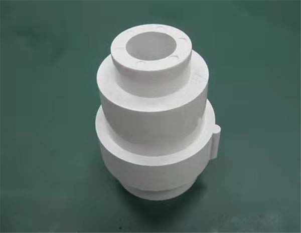
Real-world example: A mold factory processing carbide stamping model cavities used CNC EDM technology with copper electrodes. They successfully machined complex curved cavities with dimensional accuracy controlled within ±0.005 mm , solving the problem that conventional cutting could not handle the hard cemented carbide material.
What Are the Main Process Types and Applications?
Core Process Types
| Process Type | Subcategories | Technical Characteristics | Applications |
|---|---|---|---|
| EDM die-sinking | Precision micro-EDM, small hole processing | Molding electrodes create complex cavities through profiling; micro-EDM processes micron-sized holes and narrow slits | Injection molding, die-casting mold cavities; precision nozzles, medical device micro-holes |
| EDM wire cutting | Fast wire, medium wire, slow wire | Continuously moving wire electrode cuts the workpiece; slow wire has highest accuracy; fast wire is lowest cost | Stamping dies, convex/concave dies, aerospace complex contour parts, precision tooling |
Slow wire cutting: Uses brass wire or galvanized wire as the electrode. The wire is used once (disposable). Processing accuracy reaches ±0.001 mm , surface roughness as low as Ra 0.1 μm .
Fast wire cutting: Uses molybdenum wire that is recycled (multiple passes). Lower cost but lower accuracy and surface quality. Suitable for batch processing where precision requirements are moderate.
Typical Application Fields
Mold manufacturing:
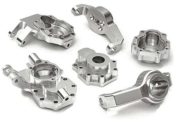
The most important application area. Stamping molds, injection molds, and die-casting molds all require EDM for complex cavities and cores. For example, an automotive bumper injection mold cavity—due to complex shape and high material hardness—can only be completed by EDM.
Aerospace components:
Titanium alloy blades and engine combustion chamber parts have high strength and heat resistance, making conventional cutting difficult. EDM achieves high-precision, deformation-free processing.
Medical device processing:
Stainless steel microporous catheters and orthopedic implants require complex textures and precise features. Precision and micro-EDM processing meet stringent biocompatibility and dimensional accuracy requirements.
Difficult-to-machine materials:
For materials like cemented carbide and ceramics, EDM is one of the most effective machining methods. For example, carbide tool edge strengthening via EDM treatment significantly improves tool service life.
What Equipment, Systems, and Components Are Involved?
Key Components of an EDM System
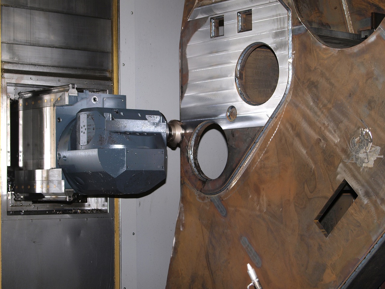
EDM machine tool:
Includes the bed, worktable, and spindle head. The worktable clamps the workpiece; the spindle head controls precise electrode movement. High-end CNC EDM machines use granite beds , offering excellent rigidity and vibration resistance—ensuring processing stability.
Pulse power supply:
The “energy core” of EDM. Provides controlled pulse currents and voltages. Adjusting pulse width (pulse duration) and pulse interval (time between pulses) controls discharge energy:
- Larger pulse width → higher discharge energy → faster processing speed → lower surface quality
- Larger pulse interval → lower discharge frequency → slower processing speed → better surface quality
Servo control system:
Maintains a stable discharge gap. When the electrode is too close to the workpiece, the system moves it back. When too far, it moves forward. High-precision servo systems are key to dimensional accuracy.
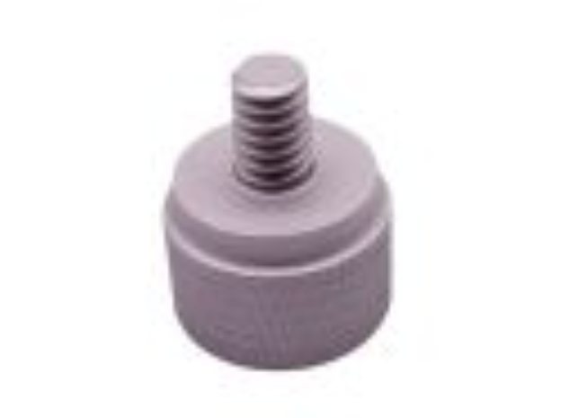
Electrodes and wire electrodes:
| Type | Materials | Characteristics |
|---|---|---|
| Die-sinking electrodes | Copper, graphite | Copper: good conductivity, low loss—high precision; Graphite: low cost, lightweight—large cavity processing |
| Wire electrodes | Brass, galvanized | Brass: high versatility; Galvanized: lower electrode loss, higher accuracy due to “discharge protection effect” of zinc layer |
Working fluid system:
Includes working fluid (kerosene, deionized water) and filtration devices. Working fluid functions: insulation, cooling, chip evacuation. Filtration removes metal debris to prevent interference with the discharge process. Slow wire cutting often uses deionized water as working fluid for higher accuracy.
What Process Parameters Control Accuracy and Surface Quality?
Core Process Parameters and Their Effects
| Parameter | Definition | Effect on Processing |
|---|---|---|
| Pulse width | Duration of a single pulse | Increasing pulse width → higher discharge energy → faster speed → rougher surface → higher electrode loss |
| Pulse interval | Time between pulses | Increasing pulse interval → lower discharge frequency → slower speed → lower electrode loss → better stability |
| Peak current | Maximum pulse current | Increasing current → higher discharge energy → faster speed → lower surface quality |
Practical technique:
- Roughing: Large pulse width, large current, small pulse interval—prioritize processing efficiency
- Finishing: Small pulse width, small current, large pulse interval—prioritize surface quality and accuracy
Machining Accuracy and Surface Quality
Accuracy metrics:
Dimensional accuracy, contour accuracy, and corner retention. For an injection mold parting surface, contour accuracy must reach ±0.002 mm . Edge and corner retention directly affects mold clamping accuracy and product quality.
Surface quality metrics:
Surface roughness (Ra) is core. Also important: surface metamorphic layer and recast layer. EDM forms a metamorphic layer a few microns thick on the workpiece surface. If too thick, it affects wear resistance and corrosion resistance.
Solution: Multiple finishing passes (polishing) reduce metamorphic layer thickness and control Ra below 0.2 μm .
Case data: A precision parts plant used a three-stage EDM process—roughing, semi-finishing, finishing. Ra dropped from 6.3 μm (rough) to 1.6 μm (semi-finish) to 0.4 μm (finish)—meeting high-precision requirements.
How Does EDM Compare to Conventional Machining?
| Aspect | EDM | Conventional Machining (Milling, Turning) |
|---|---|---|
| Contact | Non-contact (no cutting forces) | Contact (cutting forces present) |
| Material hardness | No limitation | Harder materials cause tool wear |
| Workpiece conductivity | Must be conductive | No requirement |
| Complex geometries | Excellent—cavities, undercuts, sharp corners | Limited by tool access |
| Surface finish | Ra 0.1–6.3 μm (depending on parameters) | Ra 0.4–6.3 μm |
| Heat-affected zone | Thin metamorphic layer (can be removed) | Minimal for sharp tools |
| Tool wear | Electrode wears; can be compensated | Cutting tools wear; replaced |
| Material removal rate | Lower than conventional for bulk removal | Higher for bulk material |
A Real-World EDM Success
A manufacturer producing precision injection molds for automotive components faced challenges with complex cavities in hardened steel:
- Material hardness: 58 HRC
- Conventional machining: 20% tool breakage rate; 4-week lead time
- Surface finish: Required Ra 0.4 μm for mold release
Solution: Implemented EDM with copper electrodes and a three-stage process.
Results:
- Tool breakage eliminated (non-contact)
- Lead time reduced to 10 days
- Surface finish achieved Ra 0.35 μm
- Dimensional accuracy ±0.005 mm
- Mold life increased by 30% due to no machining-induced stress
Conclusion
Spark erosion machining (EDM) is an indispensable technology for processing difficult-to-machine materials and complex geometries. Its non-contact nature eliminates cutting forces, enabling machining of hardened steels, carbides, titanium, and other materials that challenge conventional cutting. Die-sinking EDM creates complex cavities with profiling electrodes; wire EDM cuts intricate contours with high precision. Key components—pulse power supply, servo control system, working fluid—must be optimized for each application. Process parameters (pulse width, pulse interval, peak current) balance speed, accuracy, and surface quality. While EDM has lower material removal rates than conventional machining, its ability to achieve tolerances of ±0.001 mm and surface finishes of Ra 0.1 μm makes it the technology of choice for mold manufacturing, aerospace components, medical devices, and precision tooling. As manufacturing demands higher precision and more difficult materials, EDM’s role will only grow.
FAQs
Can EDM process non-metallic materials?
No. EDM requires the workpiece to be conductive. Non-metallic materials cannot form a discharge channel and cannot be processed using this technology. For non-conductive materials like ceramics or glass, other processes such as laser machining or ultrasonic machining are used.
Is there a limit to the workpiece thickness for EDM machining?
Yes. Workpiece thickness affects discharge gap stability and chip evacuation. For fast wire cutting, thickness up to 500 mm is possible. For slow wire cutting, thickness typically does not exceed 300 mm , depending on the machine model and wire electrode tension. Thicker workpieces require careful parameter adjustment to maintain stability.
How can I reduce electrode loss in EDM machining?
Three approaches: (1) Choose low-loss electrode materials—copper electrodes offer good conductivity and low loss. (2) Optimize process parameters—reduce pulse width and peak current to lower discharge energy. (3) Use negative polarity processing —workpiece connected to negative electrode, electrode to positive—reduces thermal erosion removal of the electrode. For wire EDM, galvanized wire provides a “discharge protection effect” reducing wire wear.
Does the surface metamorphic layer from EDM affect part performance?
Yes. The metamorphic layer (recast layer) formed during EDM can be a few microns thick. For high-load, high-wear applications, an excessively thick metamorphic layer reduces part service life. The layer can be removed through subsequent grinding or polishing processes. During EDM, multiple finishing passes reduce metamorphic layer thickness—achieving Ra below 0.2 μm with minimal affected depth.
What is the difference between die-sinking EDM and wire EDM?
Die-sinking EDM uses a shaped electrode that is plunged into the workpiece to create cavities. The electrode profile is transferred to the workpiece. It is used for mold cavities, blind holes, and complex 3D features. Wire EDM uses a continuously moving thin wire to cut through the workpiece like a saw. It is used for through-cutting contours, stamping dies, and parts requiring high precision in 2D profiles. Wire EDM achieves higher accuracy (±0.001 mm) than die-sinking for through-cutting applications.
Contact Yigu Technology for Custom Manufacturing
At Yigu Technology, we leverage EDM (spark erosion machining) to process difficult-to-machine materials and complex geometries that conventional methods cannot handle. Our capabilities include die-sinking EDM with copper and graphite electrodes, and wire EDM with slow wire cutting achieving ±0.001 mm accuracy and Ra 0.1 μm surface finish. We work with hardened steels, carbides, titanium alloys, and other conductive materials. Whether you need precision mold cavities, aerospace components, or medical device features, we deliver EDM solutions that meet the most demanding requirements. Contact us to discuss your EDM project.