Introduction
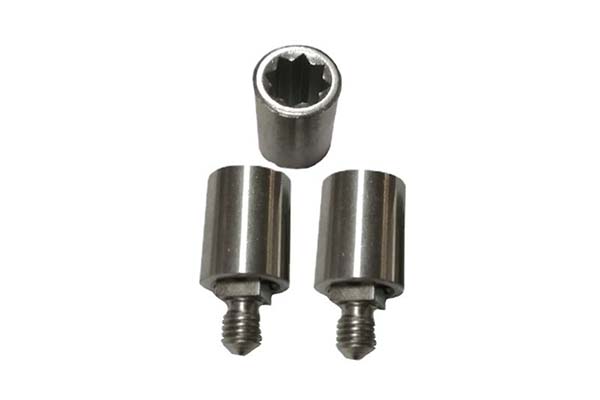
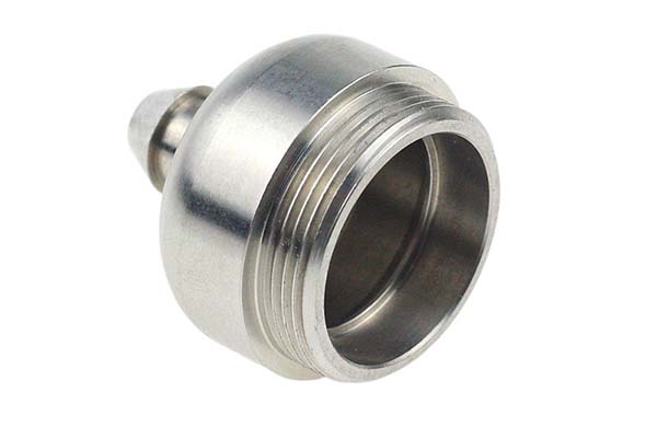
Counterbore holes are fundamental features in mechanical and manufacturing applications. They allow fasteners to sit flush with or below the surface of a part—creating smooth, even surfaces for assembly, improving aesthetics, and ensuring structural integrity. But improper design or machining of counterbore holes can lead to misaligned fasteners, improper sealing, assembly difficulties, costly rework, and product failures.
This guide covers everything you need to know about counterbore holes: definition, structure, dimensions, machining methods, accurate specification, and best practices.
What Exactly Are Counterbore Holes?
Definition and Structure
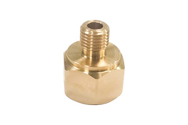
A counterbore is a cylindrical hole with a flat bottom. It is larger in diameter than another cylindrical hole located directly below it, and both share the same central axis—creating a distinct stepped structure.
| Feature | Shape | Purpose |
|---|---|---|
| Counterbore | Flat bottom | Accommodates fasteners with cylindrical heads—socket-head cap screws |
| Countersink | Conical bottom | Accommodates fasteners with conical heads—flat-head screws |
| Spotface | Shallow flat bottom | Creates flat mounting surface for locating purposes |
Components and Dimensions
| Dimension | Definition | Example |
|---|---|---|
| Counterbore diameter | Diameter of larger, upper cylindrical part | Socket-head cap screw head diameter 10 mm → counterbore diameter 12 mm (clearance for easy insertion; manufacturing tolerances) |
| Counterbore angle | Typically 90 degrees | Flat-bottomed recess perpendicular to surface—fastener head sits evenly and securely |
| Pilot hole diameter | Smaller hole beneath counterbore; defined by fastener thread diameter | M8 screw (nominal thread diameter 8 mm) → pilot hole ~6.8 mm (recommended drill size for standard metric thread) |
Standards: Engineers refer to ANSI (American National Standards Institute) or ISO (International Organization for Standardization) for detailed tables of counterbore and pilot hole dimensions.
How Are Counterbore Holes Created?
Manual Machining Methods
| Step | Process |
|---|---|
| 1. Drill pilot hole | Select drill bit appropriate for fastener thread diameter (e.g., M6 → 5.8 mm); secure workpiece firmly; align drill bit; apply steady pressure; maintain consistent speed |
| 2. Create counterbore | Select counterbore cutter with diameter larger than fastener head (e.g., 10 mm head → 12 mm cutter); mount on drill press; adjust depth stop for fastener head height + washer thickness; feed cutter slowly; apply even pressure until desired depth |
CNC Machining Techniques
| Step | Process |
|---|---|
| 1. Program coordinates | Specify X, Y, Z coordinates of hole location (e.g., X=50 mm, Y=30 mm, Z=0 at surface) |
| 2. Machine counterbore | Counterboring end mill tool; set cutting parameters: spindle speed (e.g., 1500 RPM for steel); feed rate (e.g., 0.1 mm/rev); depth of cut based on fastener head size |
| 3. Drill pilot hole | Specify pilot hole diameter based on fastener thread diameter; adjust parameters: higher spindle speed (e.g., 2000 RPM); lower feed rate (e.g., 0.08 mm/rev) for clean, accurate hole |
Critical factors: Programming accuracy; motion control system quality; cutting tool condition (wear affects quality). Regular machine maintenance and proper tool management ensure consistent, high-quality results.
How Do You Accurately Specify Counterbore Holes?
Using CAD Software
| Software | Method |
|---|---|
| SolidWorks | Select face → Features tab → Hole → Hole Wizard → Counterbore option → Choose standard (ANSI/ISO) → Specify counterbore diameter, pilot hole diameter, depth → Select fastener type (pre-defined sizes available) → Position tab → Define location on selected face |
Adhering to Standards
| Standard | Purpose |
|---|---|
| ANSI | Provides common language and guidelines; ensures consistency across manufacturers; specifies exact dimensions and tolerances for counterbore holes corresponding to fastener sizes |
| ISO | International standards; ensures compatibility across global supply chains |
Engineering Drawing Call-Outs
| Element | Symbol/Format | Example |
|---|---|---|
| Counterbore | ⌴ | Indicates counterbore feature |
| Counterbore diameter | ⌀ | ⌀15 |
| Counterbore depth | D | D8 |
| Pilot hole diameter | ⌀ | ⌀8 |
| Pilot hole depth | D | D5 |
Complete call-out example: ⌴ ⌀15 D8 ⌀8 D5 — counterbore diameter 15 mm, depth 8 mm; pilot hole diameter 8 mm, depth 5 mm.
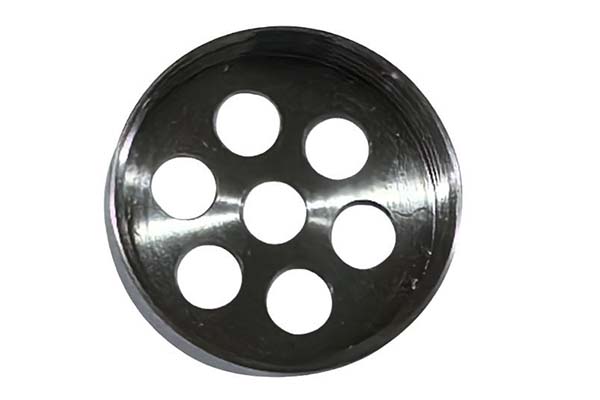
What Are Common Applications?
| Industry | Application | Benefit |
|---|---|---|
| Mechanical assembly | Flush fastener installation | Smooth, even surfaces; improved aesthetics |
| Automotive | Engine components, body panels | Structural integrity; proper sealing |
| Aerospace | Aircraft structures | Weight reduction; flush surfaces for aerodynamics |
| Electronics | Enclosures, housings | Smooth exterior; component mounting |
Conclusion
Mastering counterbore holes requires understanding their:
- Definition and structure: Cylindrical flat-bottomed hole larger than coaxial pilot hole—distinct from countersinks (conical bottom) and spotfaces (shallow flat bottom)
- Dimensions: Counterbore diameter (larger than fastener head), counterbore angle (typically 90°), pilot hole diameter (based on fastener thread diameter)—refer to ANSI/ISO standards
- Machining methods: Manual (drill pilot hole; counterbore cutter) or CNC (program coordinates; counterboring end mill; set spindle speed, feed rate, depth of cut; drill pilot hole)
- Specification: CAD software (SolidWorks Hole Wizard); ANSI/ISO standards; engineering drawing call-outs (⌴ symbol; diameter ⌀; depth D)
- Benefits: Enhanced structural integrity; improved aesthetics; smooth assembly; reduced rework; consistent quality
By accurately designing, specifying, and machining counterbore holes, engineers and manufacturers can create high-quality products that meet industry demands—ensuring proper fastener seating, reliable assembly, and long-term performance.
FAQs
What is the difference between a counterbore and a countersink?
A counterbore has a flat bottom—accommodates fasteners with cylindrical heads (socket-head cap screws). A countersink has a conical bottom—accommodates fasteners with conical heads (flat-head screws). The counterbore allows the fastener head to sit flush with or below the surface; the countersink allows the head to sit flush at an angle.
How do I determine the correct counterbore dimensions for a fastener?
Refer to ANSI or ISO standards. These provide detailed tables for different fastener sizes—counterbore diameter, pilot hole diameter, and depth. For socket-head cap screws, standard dimensions are pre-defined. For custom applications, counterbore diameter should be slightly larger than fastener head diameter (clearance for insertion and manufacturing tolerances); depth should accommodate fastener head height plus any washers.
What is the typical counterbore angle?
Standard counterbore angle is 90 degrees—provides a flat-bottomed recess perpendicular to the part surface, allowing the fastener head to sit evenly and securely. This simplifies manufacturing as most counterboring tools are designed for 90°.
What is the difference between a spotface and a counterbore?
A spotface is a shallower flat-bottomed feature—creates a flat mounting surface for locating purposes (e.g., bearing seats, washer seats). A counterbore is deeper—specifically for recessing a fastener head. Both have flat bottoms, but spotfaces are shallower and not intended to accommodate fastener head height.
How do I call out a counterbore hole on an engineering drawing?
Use the ⌴ symbol. Call out: counterbore diameter (⌀), counterbore depth (D), pilot hole diameter (⌀), and pilot hole depth (D). Example: ⌴ ⌀15 D8 ⌀8 D5 — counterbore diameter 15 mm, depth 8 mm; pilot hole diameter 8 mm, depth 5 mm.
Contact Yigu Technology for Custom Manufacturing
At Yigu Technology, we specialize in precision machining of counterbore holes and other complex features for aerospace, automotive, medical, and industrial applications. With 15 years of experience, advanced CNC machining capabilities, and ISO 9001 certification, we deliver components with tight tolerances and consistent quality.
Our expertise includes programming, tool selection, and quality control—ensuring counterbore holes meet exact specifications for proper fastener seating and reliable assembly. Contact us today to discuss your machining requirements.