Introduction
Here's a question every shop floor manager has asked at 2 AM: Why did the program pass simulation but crash on the real machine?
The truth is, CNC programming is not just writing code. It's the bridge between your 3D model and what the machine actually does. Get that bridge wrong, and you get scrap parts, broken tools, and hours of downtime.
In today's manufacturing world, the gap between what the programmer thinks and what the machine can do is widening. CAM software gets smarter every year. But machines still have physical limits. And the people who understand both? They're rare and expensive.
This article breaks down exactly how programming sets the ceiling for your machining quality, speed, and cost. We'll cover CAM tools, multi-axis challenges, parameter setting, program management, and how to close the loop between the office and the shop floor.
I. CAM Programming: Bridging the Gap
CAM Software Has Limits
Most shops use one of three big players: Mastercam, UG NX (Siemens), or PowerMILL. Each one is powerful. But none of them reads your machine's mind.
| Software | Best For | Weakness |
|---|---|---|
| Mastercam | 2.5D to 3D milling, turning | Complex 5-axis toolpaths need extra plugins |
| UG NX | Aerospace, mold making | Steep learning curve, heavy on hardware |
| PowerMILL | High-speed machining, electrode work | Weaker in turning operations |
Here's a real case. A mold shop in Ohio switched from Mastercam to UG NX for a medical device cavity. The CAM toolpaths looked perfect on screen. But the post-processor output wrong G-code for the machine's B-axis rotation. Result? First part was scrap. They lost 6 hours and $1,200 in tooling.
The problem wasn't the CAM software. It was the post-processor — the translator between CAM and machine.
Post-Processors Are the Hidden Risk
Your CAM system generates toolpaths. The post-processor converts those into G-code your machine understands. This step is where most errors hide.
Common post-processor bugs include:
- Wrong coordinate system (G54 vs. G55 mix-up)
- Tool change logic errors (spindle doesn't stop before swap)
- Macro call failures (custom M-codes don't trigger)
Pro tip: Always run a dry run with the program loader off. Watch every tool change manually. This catches 80% of post-processor errors before they hit metal.
First Article Inspection Is Non-Negotiable
Simulation passed ≠ safe to run.
Software like Vericut or NCSimul checks for collisions. But it doesn't model machine dynamics — acceleration, jerk, servo lag. A toolpath that looks smooth in sim can slam into a fixture at 8,000 mm/min on the real machine.
Rule of thumb: Never skip first article inspection. Ever.
II. Manual vs. Auto Programming
When Hand Coding Still Wins
For simple 2D parts — flat plates, slots, basic pockets — hand-written G-code is faster than opening CAM.
Example: A 100mm x 50mm aluminum bracket with 4 holes and a pocket.
- CAM setup time: 15–20 minutes
- Hand code time: 5 minutes
- Result: Same quality, less time
Manual programming shines when:
- Part has fewer than 5 features
- Tolerances are loose (±0.1mm or more)
- You need to tweak feed rates on the fly
When CAM Is the Only Option
Complex 3D surfaces — turbine blades, impellers, die cavities — require CAM. No human can calculate 50,000 toolpath points by hand.
| Feature Type | Best Method | Why |
|---|---|---|
| 2D profiles, drilling | Manual G-code | Fast setup, full control |
| 3D surfaces, molds | CAM auto-programming | Too many points for hand coding |
| Series of similar parts | Parametric/macro programming | One program, many sizes |
Macros and Parametric Code Save Time
A shop in Germany makes 200 variations of the same flange. Each one differs in bolt hole diameter and flange thickness.
Instead of writing 200 programs, they wrote one macro program with variables. The operator just inputs diameter and thickness. The program calculates everything else.
Time saved: 40 hours per month.
Error rate dropped: From 3% to nearly zero.
This is the power of parametric programming — and it's underused.
III. Multi-Axis Programming: Where It Gets Hard
Tool Axis Vector: The Core Challenge
In 3+2 or full 5-axis machining, the tool axis vector defines the tool's angle at every point. Get this wrong, and you get gouges or collisions.
| Strategy | Description | Use Case |
|---|---|---|
| Fixed axis | Tool angle stays constant | Simple 3+2 drilling |
| Continuous 5-axis | Tool angle changes smoothly | Blades, complex molds |
| Trochoidal milling | Circular tool motion | Deep cavity roughing |
Continuous 5-axis gives the best surface finish. But it demands the most skill to program.
Understanding RTCP
RTCP (Rotation Tool Center Point) keeps the tool tip at a fixed point while the machine rotates. Without RTCP, the tool tip moves in an arc during rotation. This causes dimension errors.
In practice:
- With RTCP on: The part is accurate to ±0.005mm
- With RTCP off: Errors of 0.05–0.2mm are common
Most modern machines support RTCP. But not all CAM post-processors generate correct RTCP code. Always verify.
Collision Detection: Simulation vs. Reality
| Factor | Software Simulation | Real Machine |
|---|---|---|
| Tool deflection | Often ignored | Happens under load |
| Fixture flexibility | Modeled as rigid | Can flex under clamping force |
| Machine vibration | Not simulated | Real at high feed rates |
| Thermal growth | Rarely modeled | Can add 0.02–0.05mm over 2 hours |
This is why in-process measurement (OMV) is becoming essential. The machine measures the part while cutting and adjusts the program in real time.
IV. Cutting Parameters: The Silent Programmer
Building a Material-Tool-Machine Database
Your cutting parameters should not live in one person's head. They need to be documented, tested, and stored.
| Material | Tool Type | Speed (m/min) | Feed (mm/tooth) | Depth (mm) |
|---|---|---|---|---|
| 6061 Aluminum | Carbide end mill, 10mm | 800–1200 | 0.08–0.15 | 2–5 |
| 304 Stainless | Carbide end mill, 12mm | 100–150 | 0.05–0.10 | 0.5–2 |
| H13 Tool Steel | Coated carbide, 8mm | 80–120 | 0.03–0.06 | 0.2–0.8 |
| Ti-6Al-4V | Carbide, 10mm | 60–100 | 0.04–0.08 | 0.3–1.5 |
Experience note: We worked with a shop that was machining H13 steel at 200 m/min. Tool life was 15 minutes. After dropping speed to 90 m/min and adjusting feed to 0.05 mm/tooth, tool life jumped to 90 minutes. Same tool. Same machine. Just better parameters.
Adaptive Feed and Constant Force Control
Modern controllers (Fanuc, Siemens, Heidenhain) support adaptive feed — the machine slows down in tight corners and speeds up in straight cuts. This keeps chip load constant.
Benefits:
- 20–40% faster cycle times
- Longer tool life
- Better surface finish
But it requires properly tuned parameters. Too aggressive, and the machine stutters. Too conservative, and you gain nothing.
V. Program Management: Stop Losing Knowledge
Version Control Is Not Optional
One shop had 7 versions of the same program. The operator grabbed v3 instead of v5. Result: 300 scrapped parts.
| Best Practice | Why It Matters |
|---|---|
Use naming convention: PART#_REV_DATE | Eliminates confusion |
| Lock old versions in PDM/PLM | Prevents accidental use |
| Require sign-off for changes | Creates accountability |
Standardize Process Sheets
Every program should have:
- Tool list with offset values
- Setup sketch showing fixturing
- Critical dimensions with inspection notes
- Known issues (e.g., "watch for chatter at Z=-15")
This turns tribal knowledge into company assets.
Digitizing the Master's Experience
The best programmers are the veteran machinists who've been on the floor for 20 years. But they're retiring. Their knowledge walks out the door every day.
Solutions:
- Record their parameter choices and "why" behind each decision
- Use AI-assisted programming tools (like Sandvik Coromant Capto or Autodesk Fusion) that embed expert rules
- Build expert systems that suggest parameters based on material and geometry
VI. Closing the Loop: Shop Floor Feedback
The Operator Is Your Best Debugger
Your CNC operator sees things the programmer never will:
- Chatter that only happens at a specific RPM
- A fixture that shifts after 10 parts
- A coolant nozzle that doesn't reach the cut
Build a feedback system:
| Step | Action | Tool |
|---|---|---|
| 1 | Operator logs issue | Simple form or tablet app |
| 2 | Programmer reviews | Root cause analysis |
| 3 | Program updated | New version with change note |
| 4 | Operator confirms fix | Sign-off on revised program |
This loop should take less than 24 hours. If it takes longer, your process is broken.
On-Machine Measurement Feeds Back
OMV (On-Machine Verification) uses a touch probe to measure the part while it's still in the vise.
The data flows back to the CAM system. The program auto-adjusts offsets for the next part.
Real results from a customer:
- Scrap rate dropped from 4% to 0.3%
- First article pass rate went from 72% to 96%
- Setup time reduced by 25%
Tracking OEE and Tool Life Data
| Metric | Target | How Programming Affects It |
|---|---|---|
| OEE | >85% | Bad programs cause unplanned stops |
| Tool life | Match vendor spec | Wrong parameters kill tools fast |
| Cycle time | Within 10% of quote | Inefficient toolpaths add minutes |
Collect this data. Use it to improve your next program. That's how you get better over time.
Conclusion
Does programming determine the upper limit of machining? Yes. Absolutely.
The best machine in the world can't overcome a bad program. But a great program on a decent machine will outperform a mediocre program on a $500K mill every time.
Programming is not just typing G-code. It's translating process knowledge into digital instructions that the machine can execute, repeat, and improve.
For shop owners and managers, here's what to do:
| Area | Action |
|---|---|
| Tools | Invest in CAM with good post-processors. Test before production. |
| Process | Standardize program management. Close the feedback loop. |
| People | Train programmers on the shop floor. Train operators on basic G-code. |
The shops that win in the next decade won't just have the best machines. They'll have the best programs — and the systems to keep getting better.
FAQ
Does better programming always mean faster machining?
Not always. A faster program that breaks tools or makes scrap is slower overall. Good programming optimizes for total cost, not just cycle time.
How do I know if my post-processor is correct?
Run a dry cycle with paper taped to the spindle. The paper will show the tool's actual path. Compare it to the CAM simulation.
Is manual G-code programming still worth learning?
Yes. For simple parts, it's faster than CAM. And understanding G-code helps you debug CAM programs when things go wrong.
What's the biggest cause of CNC crashes from bad programming?
Wrong tool length offsets and missing work coordinate shifts after tool changes. These two account for over 60% of crash incidents.
Can AI replace CNC programmers?
Not yet. AI can suggest parameters and detect collisions. But it can't replace the judgment of an experienced machinist who knows when to push and when to play it safe.
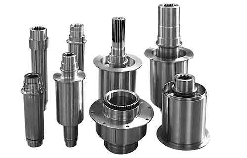
Contact Yigu Technology for Custom Manufacturing
Need precision CNC machining with expert programming that actually works on your parts? Yigu Technology delivers custom manufacturing solutions with tight tolerances, smart programming, and real shop floor experience.
📞 Get a quote today — let's close the gap between your design and your finished part.