Introduction
You need a part that resists chemicals, stands up to wear, and costs less than metal. Maybe it is a guide for a conveyor system. Maybe it is a prototype that needs to be functional, not just visual. Maybe it is a cutting board that will see daily use in a commercial kitchen.
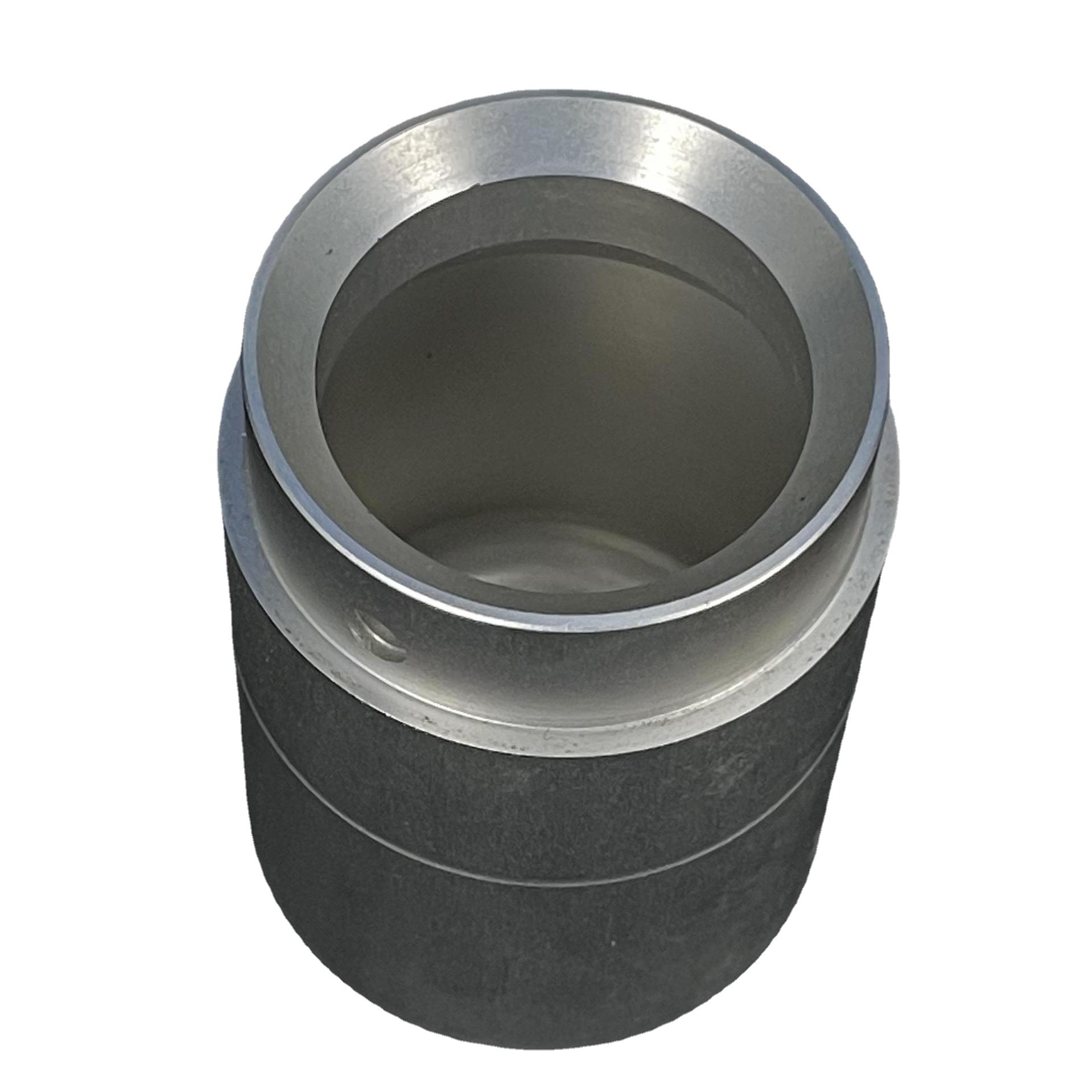
High-Density Polyethylene (HDPE) is the material for these jobs. It is tough, lightweight, and resistant to almost everything—acids, alkalis, alcohols, and most solvents. It is FDA-approved for food contact. It machines easily. And it costs a fraction of what metal would.
But machining HDPE is not without challenges. Its low hardness means it deflects under cutting forces. Its poor thermal conductivity means heat builds up quickly, causing melting and surface defects. Its stringy chips can clog tools and wrap around spindles.
At Yigu Technology, we machine HDPE for food processing, medical, automotive, and industrial clients. This guide covers the material’s properties, machining strategies, tool selection, and quality control methods that deliver consistent results.
What Makes HDPE Unique?
A Versatile Thermoplastic
HDPE is a thermoplastic—it softens when heated and hardens when cooled. This property makes it processable, but it also means heat management during machining is critical.
| Property | Value | Implication for Machining |
|---|---|---|
| Shore D Hardness | 60–70 | Soft; prone to deflection |
| Melting Point | 120–130°C | Heat causes melting; manage with cooling |
| Density | 0.941–0.965 g/cm³ | Lightweight; reduces shipping costs |
| Chemical Resistance | Excellent | Suitable for food, chemical applications |
| Thermal Conductivity | Poor | Heat accumulates at cutting zone |
How HDPE Compares to Other Plastics
| Property | HDPE | PVC (Rigid) | PP (Polypropylene) |
|---|---|---|---|
| Shore D Hardness | 60–70 | 70–90 | 50–60 |
| Melting Point | 120–130°C | 100–260°C | 160–170°C |
| Chemical Resistance | Excellent | Very Good | Very Good |
| Density (g/cm³) | 0.94–0.96 | 1.3–1.45 | 0.90–0.92 |
| Machinability | Good | Moderate | Good |
HDPE sits in the middle of the hardness range. It is softer than rigid PVC but harder than polypropylene. This softness is both an advantage (easy to cut) and a challenge (tends to deflect).
Key Properties That Affect Machining
Low hardness (Shore D 60–70): The material is soft. Cutting tools can push it rather than cut it. Workpiece deflection is common, especially in thin sections.
Poor thermal conductivity: Heat does not dissipate quickly. It builds up at the cutting zone. If temperatures exceed 120°C, the material softens and can melt, causing surface defects.
Stringy chips: HDPE produces long, continuous chips that can wrap around tools and spindles. These chips must be managed to prevent clogging.
Work hardening: Repeated cutting in the same area can increase surface hardness. This is less severe than in metals, but it can affect surface finish if not managed.
What Machining Processes Work Best?
Milling
Milling is the most common process for HDPE. It handles complex shapes, pockets, and contours.
| Parameter | Recommended Range | Notes |
|---|---|---|
| Cutting speed | 100–150 m/min | Higher speeds increase heat; stay moderate |
| Feed per tooth | 0.1–0.2 mm/tooth | Balanced for chip formation |
| Depth of cut (rough) | 1–3 mm | Aggressive but watch deflection |
| Depth of cut (finish) | 0.1–0.5 mm | Light passes for surface finish |
Tool selection for milling:
- 2-flute end mills are preferred. The open flute design improves chip evacuation, preventing stringy chips from packing.
- Polished flutes reduce chip adhesion.
- Helix angle of 20–30° minimizes tool deflection in the soft material.
Turning
Turning is used for cylindrical parts like rollers, bushings, and spacers.
| Parameter | Recommended Range | Notes |
|---|---|---|
| Spindle speed | 1,000–2,000 RPM | Moderate speeds prevent heat buildup |
| Feed rate | 0.1–0.3 mm/rev | Higher feeds possible with rigid setups |
| Depth of cut | 1–3 mm (rough); 0.2–0.5 mm (finish) |
Tool selection for turning:
- Sharp inserts with positive rake angles
- Polished rake faces to reduce chip adhesion
- Chip breakers to break stringy chips
Drilling
Drilling HDPE requires attention to chip evacuation. Long, stringy chips can pack in the flutes and break the drill.
| Parameter | Recommended Range | Notes |
|---|---|---|
| Cutting speed | 50–100 m/min | Lower speeds for deep holes |
| Feed rate | 0.05–0.15 mm/rev | |
| Point angle | 118° | Standard twist drills work well |
Peck drilling is essential. Drill 2–3 mm, retract to clear chips, then continue. This prevents chip packing and heat buildup.
Precision Machining
HDPE can achieve respectable tolerances with proper setups.
| Tolerance Level | Achievable | Conditions |
|---|---|---|
| Standard | ±0.05 mm | General machining |
| Precision | ±0.03–0.05 mm | Rigid fixtures, sharp tools |
| High precision | ±0.02 mm | Controlled environment, multi-axis machines |
Comparison to rigid plastics:
Rigid plastics like PVC can achieve ±0.02 mm. HDPE’s flexibility makes ±0.03–0.05 mm more typical. For critical applications, design with these tolerances in mind.
How to Select and Maintain Tools?
Tool Materials
| Tool Material | Suitability | Notes |
|---|---|---|
| HSS (High-Speed Steel) | Low-volume, prototypes | Cost-effective; sharpens easily |
| Carbide (K10) | High-volume production | 3× longer tool life than HSS |
| Coated carbide | Extended life, high finish | TiN or DLC coatings reduce friction |
HSS tools are adequate for small runs and prototypes. They are inexpensive and can be resharpened multiple times. For production runs exceeding 100 parts, carbide tools pay for themselves through longer life and consistent quality.
Tool Coatings
| Coating | Benefit | Life Extension |
|---|---|---|
| TiN (Titanium Nitride) | Reduces friction; extends life | 20–30% |
| DLC (Diamond-Like Carbon) | Low friction; high surface finish | 30–50% |
DLC coatings are particularly effective for HDPE. They reduce chip adhesion and allow smoother cutting, which translates to better surface finish.
Tool Geometry
| Feature | Recommendation | Why |
|---|---|---|
| Flute count | 2-flute for milling | Better chip evacuation |
| Helix angle | 20–30° | Minimizes tool deflection |
| Flute finish | Polished | Reduces chip adhesion |
| Rake angle | Positive (10–15°) | Reduces cutting forces |
Tool Wear Management
HDPE’s stringy chips can cause abrasive wear on tool flutes. While the material is soft, the continuous chip flow can polish or wear cutting edges over time.
Monitoring:
- Inspect tools every 100–200 parts
- Look for dull edges or chip adhesion
- Replace or sharpen when surface finish deteriorates
Sharpening HSS tools:
HSS tools can be resharpened 3–5 times before replacement. Maintain sharp edges—dull tools generate heat and cause melting.
How to Manage Heat and Chips?
Thermal Management
HDPE’s poor thermal conductivity means heat stays in the cutting zone. If temperatures exceed 120°C, the material softens and can melt.
Strategies to control heat:
| Strategy | How It Helps |
|---|---|
| Moderate cutting speeds | 100–150 m/min for milling; 1,000–2,000 RPM for turning |
| Sharp tools | Reduce friction; cut rather than rub |
| Compressed air | Cools cutting zone; clears chips |
| Mist coolant | Provides cooling without soaking material |
| Avoid dwell | Keep tool moving; lingering causes heat buildup |
Coolant selection:
- Compressed air is often sufficient for HDPE
- Mist coolant can be used for heavier cuts
- Flood coolant is rarely needed and can be messy with stringy chips
Chip Control
HDPE produces long, stringy chips that can:
- Wrap around the tool
- Pack into flutes
- Scratch the workpiece surface
- Clog chip conveyors
Chip control strategies:
| Strategy | How It Helps |
|---|---|
| 2-flute tools | More space for chip evacuation |
| Polished flutes | Chips slide off rather than stick |
| Peck drilling | Breaks chips in hole operations |
| Compressed air | Blows chips away from cutting zone |
| Chip breakers | Inserts with chip breakers break long chips |
Real-World Example:
A shop machining HDPE conveyor guides was struggling with chips wrapping around the end mill. Switching from 4-flute to 2-flute end mills and adding compressed air directed at the cutting zone solved the problem. Chip evacuation improved, and surface finish was consistently smooth.
What Surface Finish and Tolerances Are Achievable?
Surface Finish
| Finish Level | Ra Value | Method |
|---|---|---|
| Standard machined | 1.0–2.0 μm | Standard parameters, sharp tools |
| Smooth finish | 0.6–1.0 μm | Optimized parameters, polished tools |
| High finish | 0.2–0.6 μm | DLC-coated tools, light finishing pass |
Achieving good finish:
- Use sharp tools—dull tools cause melting and rough surfaces
- Maintain moderate speeds—too fast causes melting; too slow causes rubbing
- Use light finishing passes (0.1–0.2 mm depth)
- Apply compressed air to clear chips and cool
Dimensional Tolerances
| Tolerance Level | Achievable | Conditions |
|---|---|---|
| General | ±0.1 mm | Basic machining, standard setups |
| Precision | ±0.05 mm | Sharp tools, rigid workholding |
| High precision | ±0.03 mm | Temperature-controlled environment, careful fixturing |
Thermal expansion consideration:
HDPE expands at 150–200 μm/m·K. A 100 mm part can change size by 0.015–0.020 mm for every 1°C temperature change. For tight tolerances:
- Machine in a temperature-controlled environment (20–22°C)
- Allow parts to stabilize before final measurement
- Measure with CMM in controlled conditions
Inspection Methods
| Method | Purpose | Typical Accuracy |
|---|---|---|
| CMM (Coordinate Measuring Machine) | Dimensional verification | ±0.001 mm |
| Surface roughness tester | Ra value | ±0.01 μm |
| Optical comparator | Edge profiles, small features | ±0.005 mm |
| Visual inspection | Surface defects, melt marks | N/A |
What Post-Machining Treatments Are Needed?
Deburring
HDPE can leave sharp edges after machining. For applications where parts contact skin or food, deburring is essential.
Methods:
- Abrasive pads (220–400 grit) for manual deburring
- Vibratory finishing for batch deburring
- Hand scraping with deburring tools
Polishing
For applications requiring smooth surfaces—food processing, medical, consumer products—polishing improves finish and cleanliness.
Method:
- Wet sand with 400–600 grit sandpaper
- Progress to 800–1000 grit for higher finish
- Use compressed air to clear debris
Annealing (Stress Relief)
Large or thick HDPE parts can develop internal stresses during machining. These stresses can cause warping over time.
Annealing process:
- Heat to 80°C
- Hold for 1 hour per 25 mm of thickness
- Cool slowly to room temperature
Annealing is not required for all parts. For small, simple parts, it is unnecessary. For large, complex parts or those requiring tight tolerances, it improves dimensional stability.
Where Is HDPE Used?
Food Processing Equipment
HDPE’s FDA approval and chemical resistance make it a standard material in food processing.
| Application | Why HDPE |
|---|---|
| Conveyor belts and guides | Low friction; resists food acids |
| Cutting boards | Durable; dishwasher safe; non-porous |
| Chutes and hoppers | Smooth surface; easy to clean |
| Storage bins | Chemical-resistant; lightweight |
Medical Components
For non-implantable medical applications, HDPE offers biocompatibility and sterilization compatibility.
| Application | Why HDPE |
|---|---|
| Surgical instrument trays | Easy to sterilize; chemical-resistant |
| Drug delivery housings | Biocompatible; cost-effective |
| Diagnostic equipment components | Dimensionally stable; easy to machine |
Automotive Parts
HDPE’s lightweight and fuel resistance suit automotive applications.
| Application | Why HDPE |
|---|---|
| Fuel system components | Resists gasoline and diesel |
| Interior trim | Lightweight; durable |
| Cable insulation | Electrical insulating properties |
Industrial Components
| Application | Why HDPE |
|---|---|
| Gears | Low friction; wear-resistant |
| Guides and rails | Smooth surface; self-lubricating |
| Conveyor components | Impact-resistant; lightweight |
Prototyping
HDPE is excellent for functional prototypes. It machines quickly, costs little, and allows designers to test form, fit, and function before committing to production tooling.
How to Optimize Cost and Efficiency?
Material Cost
HDPE is relatively inexpensive—$1–3 per kg depending on form and quantity. But material waste adds up.
Waste reduction strategies:
- Nesting parts in sheet stock to maximize yield (10–15% material savings)
- Using standard stock sizes to minimize offcuts
- Designing for nesting where multiple parts share a sheet
Machining Time
Cycle time directly affects cost. Optimizing parameters within safe limits reduces time without compromising quality.
| Parameter Change | Impact |
|---|---|
| Feed rate from 0.1 to 0.15 mm/tooth | 30% faster cycle time |
| Cutting speed optimized for material | 20–30% faster material removal |
| Reduced tool changes | 10–15% time savings |
Real-World Example:
A shop producing HDPE guides increased feed rate from 0.1 mm/tooth to 0.15 mm/tooth while maintaining surface finish. Cycle time dropped by 30% with no increase in reject rate.
Tool Cost
| Volume | Recommended Tool | Cost Strategy |
|---|---|---|
| Low (1–100 parts) | HSS | Acceptable wear; resharpen 3–5 times |
| Medium (100–1,000 parts) | Carbide | Longer life; fewer tool changes |
| High (1,000+ parts) | Coated carbide | Maximum life; consistent quality |
Labor Cost
Automation reduces labor cost, especially for high-volume runs.
Strategies:
- Multi-axis machining completes parts in fewer setups
- Robotic loading/unloading for production runs
- Scheduling similar parts together to minimize tool changes (up to 20% time savings)
Yigu Technology's Perspective
At Yigu Technology, we machine HDPE for clients across food processing, medical, automotive, and industrial sectors. Our approach balances efficiency with quality:
- Tool selection: 2-flute end mills with polished flutes for chip control; carbide for production runs
- Parameter optimization: Cutting speeds 100–150 m/min; feed rates balanced for chip formation
- Thermal management: Compressed air cooling; moderate speeds to prevent melting
- Quality control: CMM inspection for critical dimensions; surface finish verification
- Cost optimization: Part nesting; batch scheduling; tool life management
We understand that HDPE’s flexibility is both its strength and its machining challenge. Our processes are designed to work with the material, not against it.
Conclusion
HDPE is a forgiving material that machines well when you understand its characteristics. Its low hardness means it cuts easily. Its poor thermal conductivity means you must manage heat. Its stringy chips mean you must prioritize chip evacuation.
Success comes from:
- Sharp tools (2-flute end mills, polished flutes)
- Moderate speeds (100–150 m/min)
- Compressed air cooling to prevent melting
- Peck drilling to clear chips
- Rigid workholding to prevent deflection
When these practices are followed, HDPE delivers reliable parts at low cost, across applications from food processing equipment to automotive components to functional prototypes.
FAQ
Why does HDPE produce stringy chips, and how do I manage them?
HDPE’s low melt strength and high ductility cause it to form long, continuous chips rather than breaking into small pieces. To manage stringy chips:
- Use 2-flute end mills with polished flutes for better chip evacuation
- Apply compressed air directed at the cutting zone to blow chips away
- Use peck drilling for hole operations
- Consider chip breaker tools for turning operations
Can HDPE be machined to the same tolerances as rigid plastics like PVC?
HDPE’s flexibility makes tight tolerances harder to achieve than with rigid plastics. While PVC can reach ±0.02 mm, HDPE typically achieves ±0.03–0.05 mm. To maximize precision:
- Use rigid fixtures that prevent part movement
- Apply low feed rates (0.05–0.1 mm/tooth) for finishing
- Machine in a temperature-controlled environment to manage thermal expansion
- Allow parts to stabilize before final measurement
What post-machining treatments are essential for HDPE parts?
Three treatments are commonly applied:
- Deburring: Removes sharp edges—essential for consumer and medical parts. Use abrasive pads or vibratory finishing.
- Polishing: Improves surface smoothness for food processing applications. Use wet sanding with 400–600 grit.
- Annealing: Relieves internal stresses in large or thick parts. Heat to 80°C for 1 hour per 25 mm thickness, then cool slowly.
For food-grade applications, ensure all post-processing methods leave surfaces that are smooth and easy to clean.
What is the best tool material for HDPE machining?
For low-volume runs (1–100 parts), HSS tools are cost-effective and perform well. For high-volume production, carbide tools (grade K10) offer 3× longer tool life. DLC-coated carbide provides the best surface finish and longest life for critical applications. All tools should have polished flutes to reduce chip adhesion.
How do I prevent melting when machining HDPE?
Melting occurs when heat builds up at the cutting zone. Prevention strategies:
- Use sharp tools—dull tools generate friction heat
- Maintain cutting speeds in the 100–150 m/min range (not higher)
- Apply compressed air to cool the cutting zone
- Avoid dwelling—keep the tool moving
- Use light depths of cut (0.1–0.5 mm) for finishing passes
If you see melted material on the tool or workpiece, reduce speed or increase cooling immediately.
Contact Yigu Technology for Custom Manufacturing
At Yigu Technology, we specialize in CNC machining of HDPE and other engineering plastics. Our capabilities include 3-axis and 5-axis milling, CNC turning, and multi-process manufacturing. We serve the food processing, medical, automotive, and industrial sectors with precision components.
Our HDPE machining expertise includes:
- Tool selection: 2-flute polished end mills; DLC-coated carbide for high finish
- Parameter optimization: Balanced speeds and feeds for chip control
- Thermal management: Compressed air cooling to prevent melting
- Quality control: CMM inspection; surface finish verification
Whether you need prototypes, industrial components, or food-grade parts, we deliver reliable, cost-effective HDPE components.
Contact us today to discuss your HDPE machining project.