Introduction
Polycarbonate (PC) is one of the most versatile engineering thermoplastics available. It combines exceptional impact strength, optical clarity, and thermal resistance in a single material. From bulletproof windows and automotive headlights to medical devices and smartphone cases, PC delivers performance where other plastics fail.
But injection molding PC is not forgiving. Its sensitivity to moisture, narrow processing window, and tendency toward stress cracking challenge even experienced manufacturers. Improper drying causes voids and brittleness. Incorrect temperatures lead to degradation or short shots. Poor mold design creates warpage that ruins precision parts.
This guide covers everything you need to know about injection molding polycarbonate. You will learn material properties, process parameters, mold design considerations, quality control methods, and applications. By the end, you will have the knowledge to produce consistent, high-quality PC parts.
What Makes Polycarbonate a High-Performance Material?
Polycarbonate’s unique combination of properties makes it suitable for demanding applications.
Optical Clarity
PC offers light transmission rates up to 90% , rivaling glass. This makes it the material of choice for:
- Lenses and optical components
- Face shields and safety glasses
- Transparent housings and windows
Unlike glass, PC is virtually unbreakable, providing safety where glass would shatter.
Impact Strength
PC has outstanding impact resistance—60–80 kJ/m² (notched Izod). This is significantly higher than:
- ABS: 20–30 kJ/m²
- Polypropylene: 5–10 kJ/m²
- Acrylic (PMMA): 1–3 kJ/m²
This toughness makes PC ideal for:
- Safety equipment (helmets, goggles)
- Automotive parts
- Protective enclosures
Thermal Properties
| Property | Value | Significance |
|---|---|---|
| Glass transition temperature (Tg) | ~145°C | Maintains properties up to this temperature |
| Heat deflection temperature (HDT) | 130–140°C | Withstands high-temperature environments |
| Continuous service temperature | Up to 120°C | Suitable for near-heat applications |
PC performs where materials like ABS would soften or deform.
Dimensional Stability
PC has a low coefficient of thermal expansion (65–70 × 10⁻⁶ /°C). This means:
- Parts maintain shape across temperature changes
- Precision assemblies stay aligned
- Less warpage during cooling
Chemical Resistance
PC resists:
- Dilute acids
- Alcohols
- Oils and greases
- Aliphatic hydrocarbons
Not resistant to:
- Strong solvents (acetone, benzene)
- Alkalis
- Aromatic hydrocarbons
Melt Flow and Grades
Melt flow rate (MFR) ranges from 5 to 40 g/10min (at 300°C/1.2kg):
- Lower MFR – Higher strength; suitable for structural parts
- Higher MFR – Better flow; fills complex molds easily
Specialized grades:
| Grade Type | Properties | Applications |
|---|---|---|
| Flame retardant | UL94 V-0 rating | Electronics enclosures |
| UV-stabilized | Resists yellowing | Outdoor applications |
| Medical grade | Biocompatible | Medical devices |
| Glass-filled | Increased stiffness | Structural components |
How Do You Process PC in Injection Molding?
PC requires precise control at every stage. The material is unforgiving of shortcuts.
Drying Requirements
PC is highly hygroscopic. It absorbs moisture from the air. During processing, moisture turns to steam, causing:
- Hydrolysis – Polymer chains break down; molecular weight drops
- Voids and bubbles – Internal defects
- Splay marks – Surface defects
- Brittleness – Reduced impact strength
Drying specifications:
| Parameter | Requirement |
|---|---|
| Temperature | 120–130°C |
| Time | 4–6 hours |
| Equipment | Dehumidifying dryer (not just hot air) |
| Target moisture | Below 0.02% |
Important: Dried PC should be used within 1–2 hours or stored in a sealed container. Re-dry if exposed to ambient air.
Melt Temperature Control
Melt temperature is critical. PC has a narrow processing window.
| Condition | Temperature | Result |
|---|---|---|
| Too low | Below 280°C | Poor flow; short shots; high viscosity |
| Optimal | 280–320°C | Good flow; proper properties |
| Too high | Above 330°C | Degradation; discoloration; gas formation |
Temperature profile:
- Feed zone: 260–280°C
- Compression zone: 280–300°C
- Metering zone: 290–310°C
- Nozzle: 280–300°C
Injection Parameters
| Parameter | Typical Range | Notes |
|---|---|---|
| Injection pressure | 80–150 MPa | Higher for thin walls or complex geometries |
| Injection speed | Moderate to high | Fast enough to fill before cooling; avoid excessive shear |
| Holding pressure | 50–80% of injection pressure | Compensates for shrinkage |
| Back pressure | 5–15 bar | Improves melt homogeneity |
| Screw speed | 50–100 RPM | Avoid excessive shear heating |
Cooling and Cycle Time
PC has a relatively high melting point and requires sufficient cooling.
| Parameter | Typical |
|---|---|
| Cooling time | 60–70% of total cycle |
| Mold temperature | 60–100°C |
| Cycle time | 30–90 seconds (depends on part size) |
Cooling tips:
- Uniform cooling prevents warpage
- Use cooling channels 8–12 mm from cavity surface
- Consider conformal cooling for complex geometries
Process Optimization
When troubleshooting:
| Problem | Likely Cause | Solution |
|---|---|---|
| Short shots | Low melt temp; low pressure | Raise temperature; increase pressure |
| Flash | Excessive pressure; worn mold | Reduce pressure; repair mold |
| Splay marks | Moisture | Re-dry material |
| Brittle parts | Degradation; moisture | Lower melt temp; improve drying |
| Voids | Moisture; poor venting | Extend drying; add vents |
How Should You Design Molds for PC?
Mold design directly affects part quality, especially for optical applications.
Mold Flow Analysis
Mold flow analysis is essential for PC. It simulates how the material fills the cavity, identifying:
- Air traps that cause voids
- Weld lines that affect strength and appearance
- Uneven filling that causes warpage
- Pressure drops that cause short shots
Investing in analysis before cutting steel prevents costly mold modifications.
Mold Materials
PC’s high melt temperature requires durable mold materials.
| Material | Best For | Notes |
|---|---|---|
| H13 tool steel | High-volume production | Excellent heat resistance; wear resistance |
| P20 steel | Medium-volume | Good balance; lower cost |
| Stainless steel | Optical or medical parts | Corrosion resistance; polishability |
Cooling Channel Design
| Feature | Recommendation |
|---|---|
| Channel distance from cavity | 8–12 mm |
| Channel diameter | 6–10 mm |
| Channel layout | Balanced; follow part contour |
| Coolant temperature | 60–80°C |
Uniform cooling prevents warpage and maintains optical clarity.
Venting Requirements
PC can trap air during filling. Proper venting prevents:
- Burn marks from compressed air
- Incomplete filling
- Voids
| Vent Feature | Specification |
|---|---|
| Vent depth | 0.01–0.02 mm |
| Vent width | 5–10 mm |
| Location | End of flow paths; around features |
Gate and Runner Design
PC benefits from larger runners and gates:
- Reduces pressure drop
- Prevents premature freeze-off
- Ensures smooth flow
Gate types:
| Gate Type | Best For |
|---|---|
| Fan gate | Large, flat parts; even flow |
| Edge gate | General purpose |
| Pin gate | Small parts; minimal mark |
| Hot runner | High-volume; reduces waste; maintains temperature |
Draft Angles and Ejection
| Feature | Recommendation |
|---|---|
| Draft angle | 1–2° per side (2–3° for textured surfaces) |
| Ejector pins | Multiple; evenly distributed |
| Surface finish | Polished (mirror finish for optical parts) |
Proper draft prevents surface scratches. For optical parts, mirror-polished mold surfaces are essential for clarity.
Hot Runner Systems
Hot runners are beneficial for PC:
- Maintain consistent melt temperature
- Reduce material waste
- Improve flow balance
Requirements:
- Precise temperature control (±2°C)
- Insulation between hot runner and mold base
- Avoid dead zones where material can degrade
What Defects Occur in PC Molding and How Do You Fix Them?
Understanding common defects helps you troubleshoot quickly.
Defects and Solutions
| Defect | Appearance | Likely Cause | Solution |
|---|---|---|---|
| Warpage | Twisted or bowed part | Uneven cooling; residual stress | Balance cooling; adjust packing |
| Sink marks | Depressions on thick sections | Inadequate packing; thick walls | Increase packing time; uniform wall thickness |
| Short shots | Incomplete part | Low melt temp; low pressure | Raise temperature; increase pressure |
| Flash | Thin plastic at parting line | Excessive pressure; worn mold | Reduce pressure; repair mold |
| Voids | Internal bubbles | Moisture; poor venting | Extend drying; add vents |
| Splay marks | Silver streaks | Moisture; degradation | Re-dry material; lower melt temp |
| Brittle parts | Low impact strength | Degradation; moisture | Lower melt temp; improve drying |
| Optical haze | Cloudiness | Improper cooling; contamination | Balance cooling; clean mold |
Quality Control Methods
Optical clarity inspection:
- Use light boxes to check for haze, bubbles, or streaks
- Measure light transmission (target >85% for optical grades)
Dimensional accuracy:
- CMM or precision gauges
- Typical tolerances: ±0.03 mm for small precision parts
Mechanical testing:
- Impact strength (notched Izod)
- Tensile strength and elongation
Statistical Process Control (SPC):
Monitor key parameters:
- Melt temperature (±3°C)
- Injection pressure (±5%)
- Cycle time (±2 seconds)
What Are the Applications of PC in Injection Molding?
PC’s unique properties enable diverse applications across industries.
Optical Components
| Application | Why PC? |
|---|---|
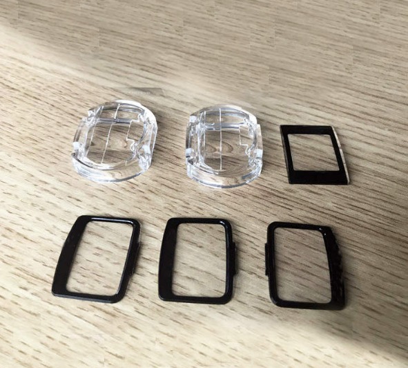
| Camera lenses | Optical clarity; impact resistance |
| Eyeglass lenses | Lightweight; shatterproof |
| Face shields | Clarity; impact protection |
| LED lenses | Thermal resistance; transparency |
Automotive
| Application | Why PC? |
|---|---|
| Headlight lenses | Thermal resistance; clarity; durability |
| Sunroofs | Impact strength; transparency |
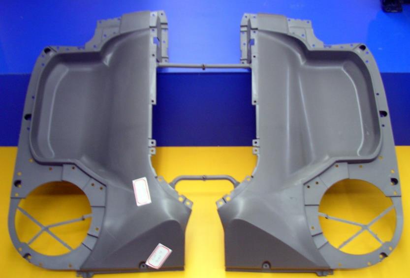
| Interior trim | Aesthetics; heat resistance |
| Instrument panels | Dimensional stability |
Electronics
| Application | Why PC? |
|---|---|
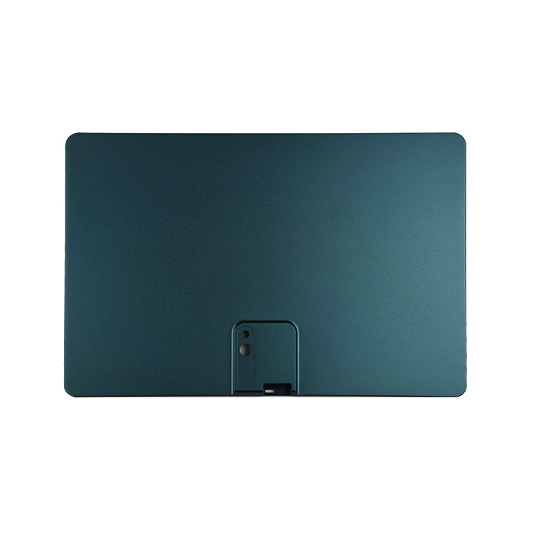
| Smartphone cases | Impact strength; thin-wall capability |
| Laptop shells | Durability; aesthetics |
| LED housings | Heat resistance; flame retardant options |
| Electrical enclosures | Insulation; impact protection |
Medical Devices
| Application | Why PC? |
|---|---|
| Syringes | Biocompatibility; clarity |
| Surgical instruments | Sterilization compatibility |
| Medical device housings | Impact resistance; cleanability |
| Drug delivery systems | Precision; chemical resistance |
Consumer Products
| Application | Why PC? |
|---|---|
| Water bottles | Impact resistance; clarity |
| Food containers | Durability; heat resistance |
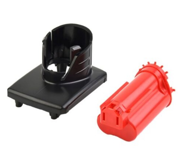
| Power tool housings | Impact strength |
| Safety helmets | Impact protection |
How Do You Post-Process PC Parts?
Post-processing enhances performance and aesthetics.
Painting and Plating
PC accepts painting and plating with proper preparation:
- Use special primers formulated for PC
- Clean surfaces thoroughly before application
- Avoid solvents that can stress-crack the material
Assembly Techniques
| Method | Suitability | Notes |
|---|---|---|
| Ultrasonic welding | Excellent | Creates strong, sealed joints |
| Adhesive bonding | Good | Use adhesives formulated for PC |
| Snap fits | Good | Design with adequate flexibility |
| Mechanical fasteners | Good | Avoid over-torquing |
Surface Treatments
| Treatment | Purpose |
|---|---|
| Hard coating | Scratch resistance (optical applications) |
| UV coating | Prevents yellowing (outdoor use) |
| Anti-fog coating | Prevents condensation (face shields) |
Heat Treatment (Annealing)
Annealing reduces residual stress and improves dimensional stability:
- Heat to 120–130°C
- Hold for 1–2 hours per 10 mm thickness
- Cool slowly (no more than 5°C per minute)
Machining and Trimming
PC machines well with:
- Sharp carbide tools
- Moderate speeds (800–1,200 RPM)
- Avoid heat buildup that causes melting or cracking
Conclusion
Polycarbonate (PC) is a high-performance engineering plastic that delivers exceptional impact strength, optical clarity, and thermal resistance. But these properties come with processing demands:
- Drying – 120–130°C for 4–6 hours; moisture below 0.02%
- Melt temperature – 280–320°C; narrow processing window
- Mold design – Balanced cooling; proper venting; polished surfaces for optics
- Process control – Precise temperature, pressure, and timing
When these requirements are met, PC produces parts with:
- Optical clarity rivaling glass
- Impact resistance unmatched by most plastics
- Dimensional stability across temperature ranges
- Durability for demanding applications
From automotive headlights to medical devices, PC continues to be the material of choice where performance matters.
Frequently Asked Questions (FAQ)
Is polycarbonate (PC) resistant to UV radiation?
Standard PC is susceptible to UV degradation, which causes yellowing and embrittlement over time. However, UV-stabilized grades are available with additives that protect against UV radiation. These grades maintain optical clarity and mechanical properties for extended outdoor use. For outdoor applications, always specify UV-stabilized PC.
Can PC be recycled?
Yes, PC is recyclable. Recycled PC retains many of its properties, though impact strength may decrease slightly depending on processing history. Clean, sorted PC waste can be reground and blended with virgin material at typical ratios of 10–25% for non-critical applications. For structural or optical parts, virgin material is recommended to ensure consistent performance.
What is the maximum temperature that PC can withstand continuously?
PC can withstand continuous use at temperatures up to 120°C. The glass transition temperature is approximately 145°C; above this, the material softens and loses mechanical properties. For short-term exposure (minutes to hours), PC can handle temperatures up to 150–160°C without immediate failure, but prolonged exposure above 120°C will cause deformation and property loss.
Why does PC require such thorough drying?
PC is hygroscopic—it absorbs moisture from the air. During injection molding, this moisture turns to steam at processing temperatures (280–320°C). The steam causes hydrolysis, which breaks the polymer chains, reducing molecular weight. This results in voids, splay marks, brittleness, and dramatically reduced impact strength. Drying to below 0.02% moisture prevents hydrolysis and preserves PC’s properties.
What is the typical shrinkage rate for PC?
PC has a relatively low and predictable shrinkage rate of 0.5–0.7% . This dimensional stability allows for tight tolerances (as low as ±0.03 mm for small parts). Mold design must account for shrinkage, but unlike materials with higher shrinkage (PP, nylon), PC’s consistency makes it suitable for precision components.
Contact Yigu Technology for Custom Manufacturing
At Yigu Technology, we specialize in polycarbonate (PC) injection molding for demanding applications across automotive, medical, electronics, and consumer goods. Our team understands the critical requirements for processing PC—from drying and temperature control to mold design and quality inspection.
Our PC molding capabilities include:
- Precision drying – Dehumidifying dryers; moisture monitoring
- Advanced process control – Closed-loop temperature and pressure control
- Mold design expertise – Flow analysis; balanced cooling; polished surfaces for optical parts
- Quality assurance – Optical clarity inspection; dimensional verification; impact testing
- Material expertise – Standard, flame-retardant, UV-stabilized, and medical grades
We produce optical components, automotive parts, medical devices, and electronics enclosures that meet the highest quality standards. Whether you need clarity, strength, or thermal resistance, our PC molding expertise delivers.
Contact us today to discuss your polycarbonate injection molding project. Let our experience help you unlock the full potential of this remarkable material.