Introduction
In machining, two fundamental processes dominate: turning and milling. Turning rotates the workpiece while a stationary cutting tool removes material—ideal for cylindrical parts. Milling rotates a multi-tooth cutter while the workpiece remains stationary—ideal for complex 3D geometries. Understanding the key differences between these processes is essential for selecting the right method for your project. This guide compares turning and milling across fundamental mechanisms, precision, surface finish, material compatibility, tooling, efficiency, and cost—helping you make informed manufacturing decisions.
How Do the Fundamental Mechanisms Differ?
The Physics of Turning
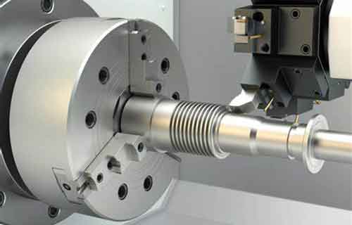
Turning rotates the workpiece while a stationary cutting tool removes material. The workpiece is held in a chuck and rotates at high speed. The cutting tool feeds linearly along the axis, removing material to create cylindrical shapes.
| Aspect | Turning Characteristics |
|---|---|
| Rotating component | Workpiece |
| Tool type | Single-point |
| Geometry capability | Axially symmetric (shafts, bushings, cylindrical rods) |
| Typical concentricity | ±0.002 mm achievable |
| Chip formation | Continuous chips under stable conditions |
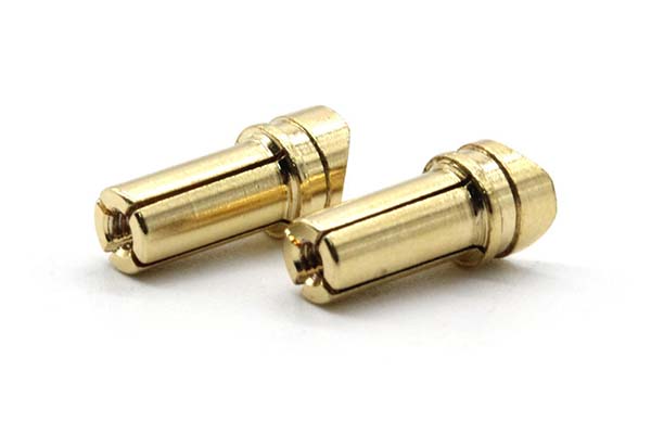
Key strength: Turning excels at parts with axial symmetry. For a stainless steel piston rod, turning achieves concentricity within ±0.002 mm —critical for engine performance.
The Dynamics of Milling
Milling uses a rotating multi-tooth cutter to remove material from a stationary workpiece. The cutter rotates at high speed while being fed into the workpiece in multiple directions.
| Aspect | Milling Characteristics |
|---|---|
| Rotating component | Cutter |
| Tool type | Multi-tooth (end mills, face mills, ball-nose mills) |
| Geometry capability | Complex 3D geometries |
| Key challenge | Vibration (chatter) from intermittent cutting |
| Material removal rate | Higher for complex shapes; 25% cycle time reduction for aluminum prototypes |
Key strength: Multi-axis flexibility. 5-axis milling machines move in three linear axes (X, Y, Z) plus two rotational axes (A, B)—producing complex components like turbine blades in a single setup.
| Comparison | Turning | Milling |
|---|---|---|
| Rotating component | Workpiece | Cutter |
| Tool type | Single-point | Multi-tooth |
| Geometry capability | Axially symmetric | Complex 3D |
| Vibration challenge | Generally less | More prone; requires optimization |
How Do Precision and Surface Finish Compare?
Tolerance Comparison
| Parameter | CNC Turning | CNC Milling |
|---|---|---|
| Typical tolerance | ±0.005 mm | ±0.02 mm |
| Achievable with advanced equipment | — | ±0.001 mm (requires precise programming) |
Turning’s stable single-point cutting process achieves tighter tolerances for cylindrical features. Medical implants like hip joint stems rely on turning for ±0.005 mm accuracy—critical for patient fit.
Surface Finish (Ra)
| Parameter | CNC Turning | CNC Milling |
|---|---|---|
| Surface finish range | 0.4 – 1.6 μm | 0.8 – 3.2 μm |
| Applications | Low friction, optical components | General machining |
Turning produces smoother surfaces—beneficial for optical components like lenses where surface quality affects performance.
Minimum Feature Size
| Parameter | CNC Turning | CNC Milling |
|---|---|---|
| Minimum feature size | 0.5 mm | 0.1 mm |
Milling’s multi-tooth cutters access and machine much smaller features—suitable for micro-mechanical components and intricate molds.
| Parameter | CNC Turning | CNC Milling |
|---|---|---|
| Typical tolerance | ±0.005 mm | ±0.02 mm |
| Surface finish (Ra) | 0.4 – 1.6 μm | 0.8 – 3.2 μm |
| Minimum feature size | 0.5 mm | 0.1 mm |
What Material Compatibility and Tooling Strategies Apply?
Tooling for Different Materials
| Material | Turning Tooling | Milling Tooling |
|---|---|---|
| Steel | Carbide inserts | Coated HSS end mills |
| Titanium | Ceramic tools (heat resistance) | Specialized carbide or diamond-coated |
| Aluminum | Carbide or HSS tools | Coated HSS end mills |
| Composites | Not typically used | Diamond tools (abrasive resistance) |
Turning example: Ceramic tools machine titanium—titanium’s low thermal conductivity causes heat buildup; ceramic tools handle high temperatures.
Milling example: Diamond tools machine composites (carbon-fiber reinforced polymers)—their extreme hardness withstands abrasiveness.
Machining Efficiency Analysis
| Part Type | Turning Efficiency | Milling Efficiency |
|---|---|---|
| Simple rotational features | 3–5 parts/hour | Slower |
| Complex shapes | Slower | 1–3 parts/hour for complex parts |
Automotive example: Milling transmission housings saves $0.20 per part compared to alternative processes—reducing manufacturing steps, improving precision, and lowering rejects.
| Aspect | Turning | Milling |
|---|---|---|
| Tooling for steel | Carbide inserts | Coated HSS end mills |
| Tooling for titanium | Ceramic tools | Specialized carbide/diamond-coated |
| Efficiency: simple rotational | Faster (3–5 parts/hr) | Slower |
| Efficiency: complex shapes | Slower | Faster (1–3 parts/hr) |
How Do You Choose the Right Process?
Part Geometry Guidelines
| Turning | Milling |
|---|---|
| Cylinders | Slots |
| Cones | Gears |
| Threads | Non-symmetric profiles |
Turning: Hydraulic cylinders require concentricity within ±0.003 mm—achieved through turning.
Milling: Helical gear milling requires precise multi-axis control to create correct tooth profile, pitch, and helix angle.
Cost Considerations
| Cost Factor | Turning | Milling |
|---|---|---|
| Upfront tooling costs | Lower (carbide insert $10–50) | Higher (end mill $50–200+) |
| Economies of scale (small batches) | Less favorable | More favorable (versatility) |
| Economies of scale (large batches) | More favorable for simple rotational parts | Less favorable for simple parts |
| Machine maintenance | Lower (simpler design) | Higher (especially high-end machines) |
| Energy consumption | Lower | Higher (high-speed multi-axis) |
| Labor costs | Lower for basic operations | Higher (skilled operators needed) |
Small-batch example: Producing 50 different prototypes—milling’s versatility allows quick tool path changes without extensive tool changes, saving costs.
Large-batch example: Thousands of identical shafts—turning’s high-speed rotation and lower tooling costs per part deliver significant savings.
Conclusion
Turning and milling serve distinct roles in manufacturing. Turning rotates the workpiece with a single-point tool—achieving ±0.005 mm tolerances, 0.4–1.6 μm surface finish, and excelling at axially symmetric parts (cylinders, cones, threads). Milling rotates a multi-tooth cutter—achieving ±0.02 mm typical tolerances (advanced: ±0.001 mm), 0.8–3.2 μm surface finish, and excelling at complex 3D geometries (slots, gears, non-symmetric profiles). Turning uses carbide inserts for steel, ceramic tools for titanium; milling uses diamond tools for composites, coated HSS for aluminum. Turning is faster for simple rotational features (3–5 parts/hour); milling is faster for complex shapes (1–3 parts/hour). Cost-wise, turning has lower upfront tooling costs and favors large-batch simple parts; milling offers better economies of scale for small-batch complex parts.
FAQs
Can a milling machine perform turning operations?
Yes, with live tooling attachments , modern milling centers can execute basic turning tasks. However, dedicated lathes offer superior precision for rotational features.
What are the common challenges in both milling and turning, and how can they be addressed?
Common issues include thermal expansion, tool wear, and insufficient clamping. Solutions include using coolant systems to manage heat, tool compensation software to account for wear, and rigid fixturing to ensure stability.
Which process is better for machining brittle materials like ceramics?
Milling with diamond-coated tools is preferable. Milling’s multi-tooth, intermittent cutting reduces stress concentrations on brittle materials. Turning requires specialized CBN (cubic boron nitride) inserts and very slow cutting speeds to prevent cracking.
Contact Yigu Technology for Custom Manufacturing
At Yigu Technology , we offer both precision turning and milling services to match your part geometry and requirements. Our CNC lathes achieve ±0.005 mm tolerances for cylindrical components. Our 3-axis, 4-axis, and 5-axis CNC mills handle complex 3D geometries—from turbine blades to custom molds. We work with steel, aluminum, titanium, and composites, providing DFM feedback to optimize your designs for manufacturability. From prototypes to production runs, we deliver the right process for your project.
Ready to choose the right machining process for your next project? Contact Yigu Technology today for a free consultation and quote. Let us help you achieve precision, efficiency, and quality in every component.