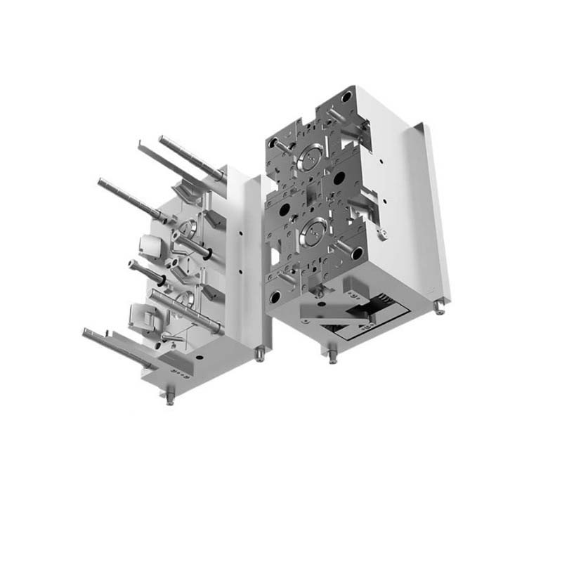
Introduction
You have a great product design. You’ve selected the right plastic. Now comes the moment of truth: the mold. A well-designed, precision-built mold produces consistent, high-quality parts for hundreds of thousands of cycles. A poorly executed tool leads to defects, delays, and endless rework.
Mastering injection mold tooling isn’t just about machining steel. It’s about understanding the interplay of material selection, design principles, manufacturing precision, and process optimization. It’s the art of balancing cost, quality, and production efficiency.
This guide walks you through the key factors that separate successful mold tooling from costly failures. Whether you’re a product designer, engineer, or manufacturing professional, these principles will help you achieve better results—cycle after cycle.
What Factors Are Critical in Mold Tooling?
Material Selection: The Foundation
Choosing the right mold material is the first and most critical decision. The material determines mold life, precision, cooling efficiency, and cost.
| Material | Hardness | Thermal Conductivity (W/m·K) | Machinability | Cost | Best For |
|---|---|---|---|---|---|
| P20 Steel | HB 280–340 | 33 | Good | Moderate | General plastic injection molds |
| H13 Steel | HRC 48–52 | 24 | Fair | Moderate–High | Hot-work molds; die casting; high-temperature plastics |
| 718 Steel | HRC 32–36 | 35 | Good | Moderate | High-volume; precision molds |
| 7075 Aluminum | HB 150–190 | 130–170 | Excellent | Low–Moderate | Fast-cooling; lightweight molds |
| 6061 Aluminum | HB 95–105 | 167 | Excellent | Low | Prototypes; low-volume production |
| Beryllium Copper | HRC 36–42 | 150–230 | Good | High | Precise temperature control; rapid cooling inserts |
| Carbide | HRA 89–93 | 20–80 | Poor | Very High | High-precision; high-wear applications |
Matching Material to Product Requirements
Based on mechanical properties:
- High strength/demanding applications: Steel (P20, 718, H13) withstands high pressures and resists deformation
- Lightweight consumer products: Aluminum offers lower cost and faster cooling
Considering heat resistance:
- High-temperature exposure: H13 steel maintains properties at elevated temperatures
- Room-temperature applications: P20 steel is cost-effective and sufficient
Taking into account wear resistance:
- Abrasive plastics (glass-filled): Carbide or high-alloy steels extend mold life
- Non-abrasive plastics: P20 or aluminum work well
Real example: A manufacturer producing glass-filled nylon automotive parts switched from P20 to a carbide-coated mold. Mold life increased from 50,000 to 200,000 cycles—justifying the higher upfront cost.
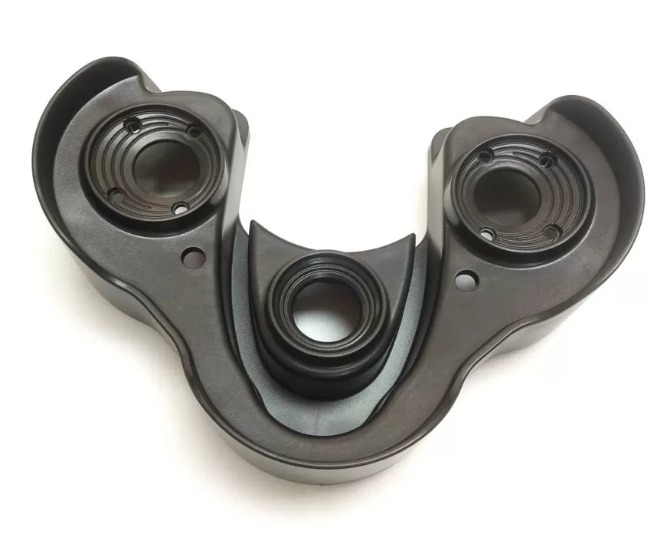
What Design Considerations Ensure Mold Success?
Understanding Product Design
Wall thickness:
Uneven wall thickness is a leading cause of molding defects. Thick sections cool slower than thin sections, creating internal stresses that cause warping, shrinkage, and cracking.
| Plastic Type | Recommended Wall Thickness |
|---|---|
| PE, PP | 1.5–3 mm |
| ABS | 1.5–4 mm |
| PC | 2–5 mm |
Key principle: Keep wall thickness as uniform as possible. Transition gradually between thick and thin sections.
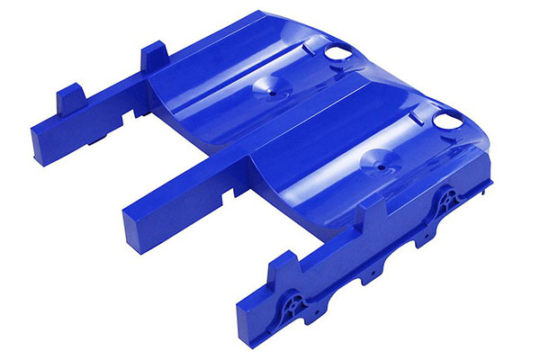
Product structure:
- Ribs: Increase strength without adding excessive wall thickness. Too thick ribs cause sink marks—keep rib thickness 50–70% of adjacent wall thickness.
- Bosses: Provide mounting points. Design with sufficient clearance for screws or inserts.
- Undercuts: Require side-action mechanisms (slides or lifters) for part ejection. Minimize undercuts where possible to reduce mold complexity.
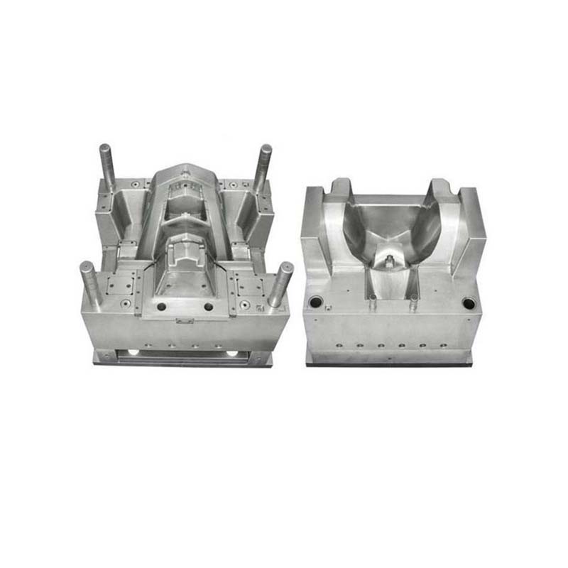
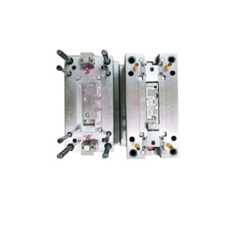
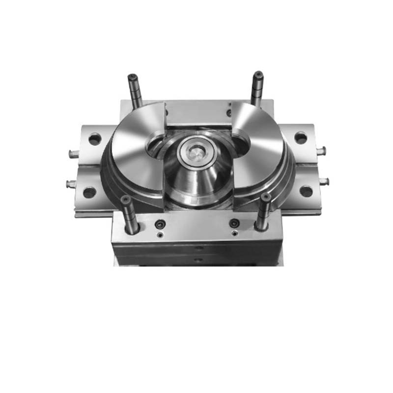
Mold Design Principles
Parting line design:
The parting line is where mold halves meet. A well-designed parting line:
- Minimizes need for complex side-action mechanisms
- Ensures good sealing to prevent flash
- Allows easy part ejection
For symmetrical parts, place the parting line along the centerline. For irregular shapes, strategically locate it to enable simple ejection.
Gate location determination:
Gate location significantly impacts part quality. Poor placement causes:
- Flow marks
- Weld lines
- Incomplete filling
- Visible gate marks
| Gate Type | Best For | Characteristics |
|---|---|---|
| Sprue gate | Large parts; high flow | Simple; leaves large mark |
| Edge gate | Flat parts | Good for uniform filling |
| Pin gate | Small, precise parts | Small mark; precise flow control |
| Submarine gate | Cosmetic parts | Self-cutting; minimal mark |
Gate placement principles:
- Position where plastic can flow evenly throughout cavity
- Avoid placing gates at thin sections where flow resistance is high
- For multi-cavity molds, ensure balanced filling to all cavities
What Manufacturing Technologies Deliver Precision?
Advanced Manufacturing Technologies
CNC Machining:
CNC (Computer Numerical Control) machining is the workhorse of mold making. It delivers:
- Precision: Tolerances as tight as ±0.001 mm
- Complex geometries: Multi-axis machines create intricate shapes
- Repeatability: Identical components for multi-cavity molds
Applications: Cavities, cores, mold bases, cooling channels
EDM (Electrical Discharge Machining):
EDM creates features that CNC tools can’t reach—sharp internal corners, deep ribs, and complex internal geometries.
| Type | Best For | Precision |
|---|---|---|
| Die-sinking EDM | 3D cavities; intricate shapes | ±0.005–0.01 mm |
| Wire EDM | Precise profiles; sharp corners | ±0.001–0.005 mm |
Application: A mold for a small electronic component with fine details required EDM to create precise cavities and channels.
Quality Control in Manufacturing
Dimensional accuracy inspection:
Coordinate Measuring Machines (CMMs) measure mold components against design specifications. Any deviation is caught early—before assembly.
What CMM measures:
- Length, width, height
- Hole diameters and positions
- Geometric features (flatness, roundness, parallelism)
Surface quality control:
Surface finish affects part appearance and release. Profilometers measure surface roughness. For high-gloss parts, mirror finishes (Ra 0.01–0.05 μm) are required.
Common surface issues:
- Scratches
- Pits
- Rough areas that cause part sticking
Polishing and finishing processes address these issues before production.
How Do You Optimize the Injection Molding Process?
Temperature Control
Barrel temperature:
Barrel temperature directly affects plastic melting and flow.
| Material | Melting Range | Impact of Low Temperature |
|---|---|---|
| PE | 110–130°C | 10°C below recommended increased short-shot defects from 5% to 15% |
| PP | 160–170°C | — |
| ABS | 200–240°C | — |
Modern machines use PID (proportional-integral-derivative) control to maintain barrel temperature within ±2°C.
Mold temperature:
Mold temperature impacts surface finish and dimensional stability.
| Condition | Effect |
|---|---|
| Higher mold temperature | Smoother surface; fewer flow marks |
| Too high | Shrinkage; warping (up to 2–3 mm for large panels) |
Control methods: Water or oil circulation systems; electric heating elements for precise control.
Pressure and Speed
Injection pressure:
Required to force molten plastic into the cavity.
| Application | Typical Pressure | Risk of Too High |
|---|---|---|
| Thin-walled parts (1–2 mm) | 80–120 MPa | Flash; internal stresses |
| Thick-walled parts | 40–80 MPa | — |
Multi-stage injection: Low pressure to fill main cavity; higher pressure to pack intricate details—reduces defect risk.
Holding pressure:
Applied after filling to compensate for shrinkage.
| Effect | Impact |
|---|---|
| Proper holding pressure | Prevents sink marks; ensures dimensional stability |
| Too low | 20% reduction increased sink mark defects from 10% to 30% |
| Too high | May cause over-packing; part sticking |
Injection speed:
Affects flow pattern and part quality.
| Speed Issue | Consequence |
|---|---|
| Too slow | Cold weld lines; incomplete filling |
| Too fast | Turbulent flow; air traps; voids |
Variable-speed injection: High speed for large-volume areas; reduced speed for intricate features—balances filling and quality.
Cycle Time Management
Components of the molding cycle:
| Stage | Typical % of Cycle |
|---|---|
| Injection | 5–15% |
| Holding | 5–15% |
| Cooling | 50–70% |
| Ejection | 5–10% |
Optimizing cooling time:
Cooling accounts for 50–70% of total cycle time. Strategies to reduce it:
- Conformal cooling channels: Follow cavity shape; provide uniform cooling. Reduced cooling time by 30% in a case study—increasing output 20%.
- High heat-transfer coolant: Water standard; heat-transfer oils for high-temperature molds
- Optimized coolant temperature: Maintain 20–30°C below desired mold temperature
Reducing other stages:
- Injection/holding: Fine-tune pressure and speed; can reduce injection time 10–20%
- Ejection: Hydraulic or pneumatic systems faster than mechanical
How Do You Troubleshoot Common Defects?
Identifying and Solving Defects
| Defect | Causes | Solutions |
|---|---|---|
| Short-shot | Insufficient pressure; clogged runner; low melt temperature | Increase pressure 5–10 MPa; raise barrel temperature 5–10°C; clean runner/gate |
| Flash | Insufficient clamping force; damaged mold; too-high pressure | Increase clamping force 10–20%; reduce injection pressure 5–10%; repair/realign mold |
| Sink marks | Insufficient holding pressure; non-uniform cooling | Increase holding pressure 10–20%; extend holding time 2–5 seconds; improve cooling in thick sections |
| Weld lines | Slow injection speed; low melt temperature; poor gate location | Increase injection speed; raise melt temperature; relocate gate |
| Warpage | Uneven cooling; non-uniform wall thickness | Redesign cooling channels; adjust mold temperature; modify part design |
Conclusion
Mastering injection mold tooling requires attention to four key areas:
- Material selection: Match material properties to your product’s requirements—strength, heat resistance, wear resistance, and production volume.
- Design considerations: Uniform wall thickness, strategic gate placement, and well-designed parting lines prevent defects and simplify manufacturing.
- Precision manufacturing: CNC machining and EDM deliver the tight tolerances required for quality molds. Rigorous inspection ensures dimensional accuracy.
- Process optimization: Control temperature, pressure, speed, and cycle time to produce consistent, high-quality parts.
Each element builds on the others. Master them all, and you’ll have molds that perform reliably—cycle after cycle, year after year.
FAQ
How can I control the barrel temperature accurately in injection molding?
Modern injection molding machines use thermocouples to measure temperature at different barrel zones. PID (proportional-integral-derivative) control algorithms adjust heating power based on measured deviations, maintaining temperature within ±2°C of the set point.
What should I do if there are flash defects in my injection-molded parts?
Flash occurs when plastic seeps between mold halves. Increase clamping force (10–20% for medium molds), reduce injection pressure slightly (5–10%), and inspect the mold for damage or misalignment. Regular maintenance prevents flash recurrence.
Why do sink marks occur in injection-molded parts and how can I solve them?
Sink marks result from shrinkage during cooling, typically in thick-walled sections or near ribs and bosses. Solutions: increase holding pressure 10–20% to push more plastic into shrinking areas, extend holding time 2–5 seconds, and improve cooling uniformity—especially around thick sections.
What’s the best mold material for glass-filled plastics?
Glass-filled plastics are highly abrasive. Carbide or high-alloy steels with wear-resistant coatings (e.g., chrome or nitriding) extend mold life. Hard anodized 7075 aluminum can work for short runs, but for high volume, steel is recommended.
How do I choose between aluminum and steel for my mold?
Consider production volume. Aluminum: 1,000–30,000 cycles; lower upfront cost; faster machining; ideal for prototypes and low-volume production. Steel: 100,000–1,000,000+ cycles; higher upfront cost; better wear resistance; essential for high-volume production. For runs under 10,000 parts, aluminum is cost-effective. For runs over 50,000 parts, steel pays for itself.
Contact Yigu Technology for Custom Manufacturing
At Yigu Technology, we’ve mastered the art of injection mold tooling through decades of experience. Our team guides you through material selection, design optimization, precision manufacturing, and process refinement to deliver molds that perform.
We offer:
- Custom mold design and manufacturing
- Material selection expertise (P20, 718, H13, aluminum, copper alloys)
- Precision CNC machining and EDM
- CMM inspection and full documentation
- Process optimization support
[Contact Yigu Technology today] to discuss your injection mold project. Let’s build the tool that brings your product to life with quality, reliability, and efficiency.