Introduction
Look at the complex parts inside an aircraft engine. Examine the core components of a modern automobile transmission. Study the delicate textures of precision molds. Behind each lies industrial milling—the precision engraver that shapes raw materials into functional components.
Industrial milling removes material through the relative motion between a rotating cutting tool and a workpiece. It creates complex geometries that other processes cannot achieve. But mastering this core manufacturing technology requires understanding equipment selection, tooling strategies, material behavior, and quality control.
This guide provides a comprehensive overview of industrial milling—from basic principles to advanced applications. Whether you are a manufacturing practitioner, technology selector, or industry learner, these insights will help you understand and apply this essential process.
What Are the Fundamentals of Milling?
To master industrial milling, start with its core logic: material removal through controlled cutting.
Core Movement and Forces
Milling combines spindle motion with feed motion:
| Component | Function | Typical Range |
|---|---|---|
| Spindle speed | Rotates cutting tool | 1000–30,000 RPM |
| Feed rate | Moves table or tool along path | 100–2000 mm/min (aluminum); 100–500 mm/min (stainless) |
Cutting forces must be balanced:
- Too high: Workpiece deformation, tool wear, spindle vibration
- Too low: Reduced efficiency
Data point: Carbide tools machining 45 steel generate cutting forces of 1000–3000 N. For every 0.5 mm increase in depth of cut, cutting force increases by 15–20%.
CNC Programming: The Command System
Modern milling relies on CNC programming with G-code:
| Code | Function | Example |
|---|---|---|
| G01 | Linear feed | Straight-line cutting |
| G02/G03 | Circular interpolation | Arc cutting |
| G54–G59 | Workpiece coordinate systems | Part positioning |
Experience tip: For complex surface machining, use CAM software (Mastercam, UG) to generate G-code, then manually optimize feed rates for critical paths. Reducing feed by 20–30% at corners effectively reduces vibration and improves surface quality.
How Do You Choose the Right Milling Machine?
Equipment selection depends on machining needs, workpiece size, and precision requirements.
Milling Machine Types and Applications
| Machine Type | Core Features | Applications | Typical Accuracy |
|---|---|---|---|
| CNC milling machine | Programmable control, multi-axis | Small-medium precision parts | ±0.005–0.02 mm |
| Machining center | Automatic tool change; milling, drilling, boring | Complex parts, mass production | ±0.003–0.015 mm |
| Horizontal milling machine | Horizontal spindle, high rigidity | Heavy cutting, deep cavities | ±0.01–0.03 mm |
| Vertical milling machine | Vertical spindle, easy operation | Simple parts, small batches | ±0.015–0.04 mm |
| Gantry milling machine | Large stroke, stable structure | Large workpieces, plates | ±0.02–0.05 mm |
| Multi-axis milling (4/5-axis) | Multi-directional cutting, single setup | Complex curved surfaces, impellers | ±0.002–0.01 mm |
| High-speed milling | Spindle speed >15,000 RPM | Soft materials, thin-walled parts | ±0.005–0.01 mm |
| Precision milling machine | Constant temperature, error compensation | Ultra-high precision parts | ±0.001–0.005 mm |
Practical Selection Guide
| Scenario | Recommended Machine | Why |
|---|---|---|
| Small-medium production, complex parts | Machining center | Reduces setups, improves efficiency |
| Large workpieces (>2 m) | Gantry milling machine | Stable structure, large stroke |
| Aerospace profiled parts (blades) | 5-axis milling | Avoids tool interference, ensures accuracy |
What Tools and Cutting Techniques Work Best?
The tool is the "tooth" of milling; cutting technique is the "bite method." Together, they determine quality and cost.
Milling Cutter Types and Materials
| Cutter Type | Best For |
|---|---|
| End mill | Side cutting, grooving |
| Face mill | Flat surfaces |
| Ball nose mill | Curved surface finishing |
| Slot mill | Groove cutting |
Tool Materials:
| Material | Hardness | Wear Resistance | Best For |
|---|---|---|---|
| Carbide | HRC 90+ | 5–10× HSS | Most industrial milling |
| High-speed steel (HSS) | Lower | Standard | Low-volume, simple jobs |
Coatings:
| Coating | Benefit | Applications |
|---|---|---|
| TiN | Hardness, lubricity | Steel processing |
| AlTiN | High-temperature resistance | High-speed cutting |
| DLC | Reduces built-up edge | Aluminum, sticky materials |
Cutting Assistance Technology
Coolant Systems:
| Type | Best For | Effect |
|---|---|---|
| Oil-based | Heavy cutting | Good lubrication |
| Water-based (emulsion) | High-speed cutting | Cools, extends tool life 2× |
Tool Life Optimization:
| Material | Challenge | Solution |
|---|---|---|
| Titanium alloys | Poor thermal conductivity | Low speed (50–100 m/min), high feed (0.1–0.2 mm/tooth), AlTiN coating |
| Hardened steel | High hardness | Low speed (1000–3000 RPM), large depth (1–3 mm) |
Chip Breaking:
- Achieved through tool groove design (spiral, corrugated) and feed adjustment
- For mild steel: 30° helix angle, feed 0.2–0.3 mm/tooth creates naturally breaking chips
Dry Milling:
- No coolant; environmentally friendly, cost-reducing
- Requires 10–20% lower cutting speed; tools must have high-temperature resistance (SiAlON ceramic)
How Do You Machine Different Materials?
Different materials require different approaches.
Metal Milling Tips
| Material | Challenges | Recommended Tools | Core Parameters | Applications |
|---|---|---|---|---|
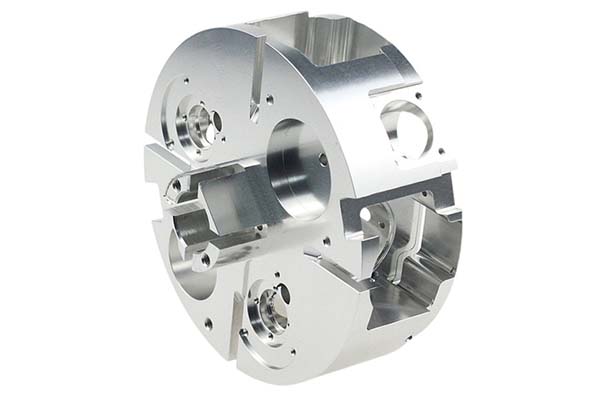
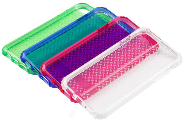
| Aluminum alloy | Sticky, built-up edge | Carbide + DLC coating | Speed 10,000–30,000 RPM; feed 500–2000 mm/min | Engine blocks, phone housings |
| Stainless steel | High hardness, poor conductivity | Carbide + AlTiN coating | Speed 1000–5000 RPM; feed 100–500 mm/min | Medical equipment, chemical parts |
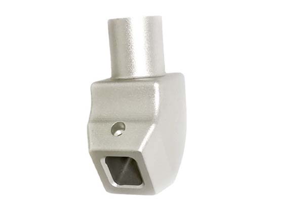
| Titanium alloy | High strength, high cutting temperature | Carbide + TiSiN coating | Speed 500–1500 RPM; feed 50–200 mm/min | Engine blades, orthopedic implants |
| 45 steel | Versatile, easy to machine | Carbide or HSS | Speed 3000–8000 RPM; feed 300–1000 mm/min | Mechanical parts, mold bases |
Special Materials and Industry Applications
Composite Materials (Carbon Fiber Reinforced Resin):
- Challenge: Fibers break easily; resin melts
- Solution: Diamond-coated tools; low speed (5000–10,000 RPM); high feed (300–800 mm/min); compressed air cooling
- Applications: UAV fuselage, aerospace structural parts
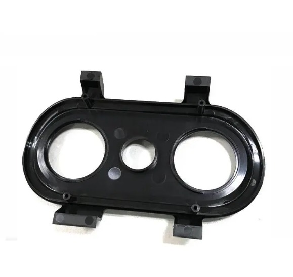
Mold Manufacturing:
- Milling is the core process—requires both precision and surface quality
- Technique: 5-axis milling + ball nose finishing achieves Ra 0.1–0.3 μm, often eliminating polishing
Automotive Parts:
- High-volume, high-precision requirements
- Solution: Machining center + special fixtures + high-pressure cooling achieves 50–100 parts/hour with tolerances ±0.01 mm
Aerospace Components:
- Landing gear, wing structures from titanium and high-strength steel
- Requirement: Multi-axis milling; solid carbide tools; layered cutting to reduce forces
How Do You Control Precision and Quality?
Precision is the lifeline of milling machining.
Key Accuracy Indicators
| Indicator | Control Method | Target Range |
|---|---|---|
| Tolerance | High-precision machines; hydraulic clamps; regular calibration | ±0.005–0.01 mm (precision parts); ±0.05–0.1 mm (general) |
| Surface roughness | Sharp tools; optimized parameters; adequate coolant | Ra ≤0.2 μm (finishing); Ra 0.8–3.2 μm (general) |
| Dimensional accuracy | Online inspection; automatic tool compensation | 95–99.5% pass rate |
Common Problems and Solutions
| Problem | Cause | Solution |
|---|---|---|
| Vibration | Low rigidity; poor parameters | Increase machine rigidity; reduce speed; increase feed; use damping tools |
| Thermal deformation | Heat from cutting | Constant temperature shop (±2°C); coolant; thermal compensation in programming (0.001–0.003 mm/°C) |
| Process monitoring | Undetected tool wear or clamping issues | Sensors monitor cutting forces, temperature; auto-stop when force rises >20% |
Quality Standards:
- ISO 9001: General quality management
- AS9100: Aerospace sector—every machining step documented and traceable
- Inspection: Coordinate measuring machines (CMM), roughness testers
Conclusion
Industrial milling is evolving toward high precision, high efficiency, and green manufacturing. 5-axis milling and high-speed technologies are becoming standard. AI-driven programming and adaptive cutting will further improve efficiency. Dry milling and minimum quantity lubrication (MQL) address environmental concerns.
For manufacturing practitioners:
- Equipment selection: Prioritize rigidity and precision reserve—avoid obsolescence as capabilities expand
- Tool investment: Quality coated tools cost more but reduce total processing cost (tool change time, scrap rate)
- Talent development: CNC programming, equipment debugging, and quality control expertise are core competitive advantages
The future belongs to those who deeply integrate technology, equipment, and talent—fully realizing the value of industrial milling to empower product innovation.
FAQs
What is the core difference between a CNC milling machine and a machining center?
The machining center has an automatic tool changer and tool magazine (holding 10–100 tools), enabling milling, drilling, and boring in one setup. CNC milling machines typically require manual tool changes, making them suitable for single-process operations.
What should I do when tools wear quickly during stainless steel machining?
Use carbide tools with AlTiN coating. Reduce cutting speed (1000–3000 RPM), increase feed, and use high-pressure emulsion cooling to prevent heat-related wear.
How can I improve surface roughness in milling operations?
Three approaches: 1) Use sharp finishing tools (ball nose mills, diamond-coated tools). 2) Optimize cutting parameters—small depth of cut, high feed rate. 3) Ensure adequate coolant lubrication to reduce tool-workpiece friction.
What types of parts are suitable for multi-axis milling?
Complex curved surfaces, profiled parts, and deep cavities—impellers, turbine blades, aerospace structural parts. Multi-axis reduces clamping setups, avoids tool interference, and improves accuracy.
How do I choose between dry milling and wet milling?
Dry milling: Suitable for cast iron, aluminum alloys—environmentally friendly, lower cost. Requires tools with high-temperature resistance (SiAlON ceramic). Wet milling: Required for difficult materials like stainless steel and titanium—better cooling and lubrication, extends tool life.
Contact Yigu Technology for Custom Manufacturing
At Yigu Technology, we combine deep milling expertise with advanced equipment to deliver precision components. With 15 years of experience, 5-axis machining centers, and ISO 9001 certification, we serve aerospace, automotive, medical, and industrial sectors.
Our team optimizes tool selection, cutting parameters, and quality control for your specific materials—from aluminum to titanium to composites. Contact us today to discuss your milling project and discover how our capabilities can empower your manufacturing.