Introduction
Injection molding of engineering plastics is the backbone of modern manufacturing, producing high-performance components for automotive, aerospace, medical, and electronics industries. Unlike commodity plastics, engineering plastics deliver exceptional mechanical strength, heat resistance, chemical stability, and dimensional precision under demanding conditions.
But with these superior properties come significant challenges. Wrong material selection leads to premature failure. Poor mold design causes warpage and dimensional inaccuracies. Improper process parameters degrade material properties. Even minor issues—like inconsistent cooling or inadequate drying—can turn a promising project into a costly ordeal.
This guide addresses these pain points directly. You will learn how to select the right engineering plastic, design molds for optimal performance, control process parameters precisely, and troubleshoot common defects. Whether you are working with ABS, polycarbonate, nylon, PEEK, or advanced composites, this guide provides actionable insights for mastering the process.
What Are Engineering Plastics and Why Do They Matter?
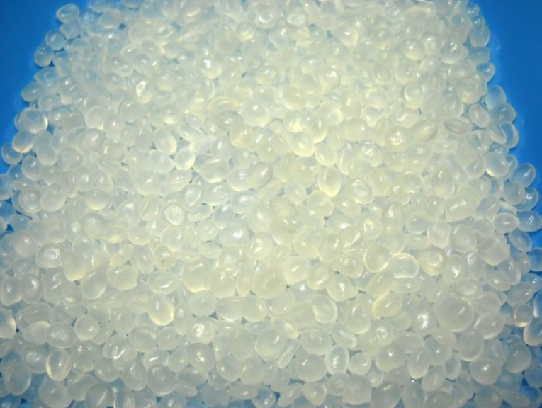
Engineering plastics are a class of high-performance polymers that offer superior mechanical, thermal, and chemical properties compared to commodity plastics (like polypropylene or polyethylene). They are designed to withstand higher stresses, temperatures, and harsh environments.
Engineering Plastics vs. Commodity Plastics
| Property | Commodity Plastics | Engineering Plastics |
|---|---|---|
| Tensile strength | 20–40 MPa | 50–200+ MPa |
| Heat deflection temperature (HDT) | 50–100°C | 100–250°C |
| Impact strength | Moderate | High to exceptional |
| Chemical resistance | Limited | Excellent (depending on material) |
| Cost | Low | Medium to high |
| Applications | Packaging; disposable goods | Structural; high-performance; medical; aerospace |
Common Engineering Plastics and Their Properties
| Material | Key Properties | Typical Applications |
|---|---|---|
| ABS | Impact resistance; good surface finish; dimensional stability | Electronics housings; automotive trim; consumer goods |
| Polycarbonate (PC) | High impact strength; optical clarity; heat resistance | Lenses; medical devices; safety equipment |
| Nylon (PA) | High strength; wear resistance; low friction | Gears; bearings; structural components |
| Acetal (POM) | Low friction; dimensional stability; stiffness | Precision gears; bushings; valves |
| PBT | Electrical properties; chemical resistance; stiffness | Connectors; automotive electronics |
| PEEK | High temperature resistance; chemical resistance; biocompatible | Aerospace; medical implants; high-performance seals |
| PEI (Ultem) | High heat resistance; flame retardancy; dimensional stability | Aerospace interiors; surgical instruments |
| PPS | Chemical resistance; thermal stability; electrical properties | Automotive underhood; industrial components |
Reinforced Engineering Plastics
Glass fiber reinforcement dramatically improves properties:
| Reinforcement | Effect |
|---|---|
| 10–20% glass fiber | Increased stiffness; improved heat resistance |
| 30–40% glass fiber | Maximum stiffness; tensile strength increase up to 300% |
| Carbon fiber | Ultra-high stiffness; lightweight; conductivity |
Trade-off: Reinforced materials increase mold wear and may affect surface finish.
How Do You Select the Right Engineering Plastic?
Material selection is the foundation of success. The wrong choice leads to failure under load, temperature, or chemical exposure.
Key Selection Criteria
Mechanical Properties
| Property | What It Measures | Typical Requirement |
|---|---|---|
| Tensile strength | Resistance to stretching | Structural parts: >50 MPa |
| Flexural modulus | Stiffness under bending | Structural parts: >2,000 MPa |
| Impact strength | Resistance to sudden loads | Consumer goods: high; precision parts: moderate |
| Wear resistance | Resistance to friction and abrasion | Gears; bearings: high |
Thermal Properties
| Property | What It Measures | Application Examples |
|---|---|---|
| Heat deflection temperature (HDT) | Temperature at which part deforms under load | Underhood automotive: >120°C |
| Glass transition temperature (Tg) | Temperature where material softens | Continuous service temperature reference |
| Continuous use temperature | Long-term heat resistance | Electronics: 100–200°C depending on material |
Chemical Resistance
Consider exposure to:
- Fuels and oils (automotive, industrial)
- Cleaning agents and disinfectants (medical)
- Solvents (electronics manufacturing)
- Acids and alkalis (chemical processing)
Special Requirements
| Requirement | Suitable Materials |
|---|---|
| Biocompatibility | Medical-grade PC, PEEK, PEI, silicone |
| Flame retardancy | UL94 V-0 rated: PC, PEEK, PEI, PPS |
| Optical clarity | PC, PMMA, clear ABS |
| UV stability | UV-stabilized grades of PC, ASA |
Material Compatibility Considerations
- Hygroscopic materials (nylon, PC, PET) require thorough drying—moisture causes voids and brittleness
- Reinforced materials (glass-filled) cause higher mold wear; require hardened tool steel
- Material pairings for multi-shot molding must be compatible to prevent delamination
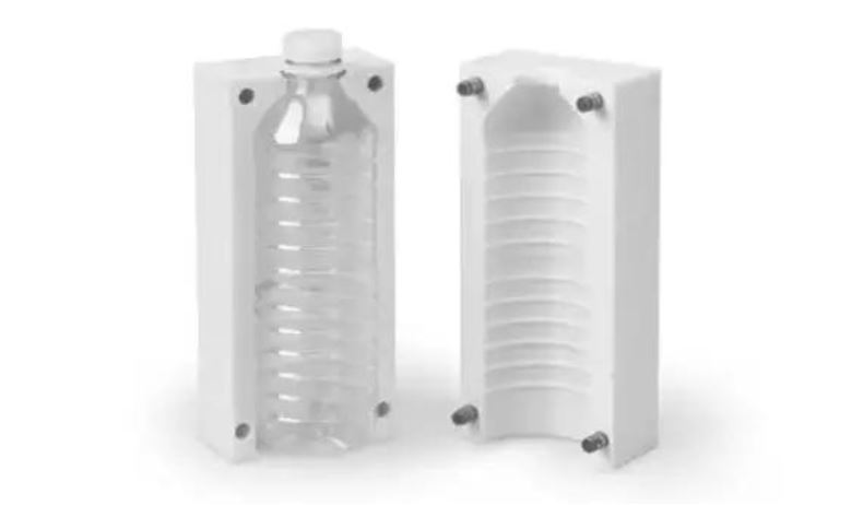
How Do You Design Molds for Engineering Plastics?
Mold design is the blueprint for quality. Engineering plastics demand precision, durability, and careful thermal management.
Mold Materials
| Mold Material | Best For | Advantages | Considerations |
|---|---|---|---|
| P20 steel | Medium-volume; general engineering plastics | Good machinability; moderate cost | Limited wear resistance |
| H13 steel | High-volume; reinforced materials | Excellent wear resistance; heat treated | Higher cost; longer lead time |
| Stainless steel | Medical; corrosive environments | Corrosion resistance; cleanability | Higher cost |
| Aluminum | Prototypes; low-volume; simple geometries | Fast lead time; lower cost | Limited cycle life |
Critical Mold Design Elements
Gate Design
| Gate Type | Best For |
|---|---|
| Pin gate | Small parts; cosmetic surfaces |
| Edge gate | General purpose; easy to machine |
| Fan gate | Large, thin parts; even flow |
| Submarine gate | Automatic degating; high-volume |
Runner Systems
| System | Advantages | Disadvantages |
|---|---|---|
| Cold runner | Simpler; lower mold cost | Material waste; longer cycles |
| Hot runner | No waste; faster cycles; better quality | Higher cost; more complex |
Cooling Channel Design
- Channels should be 1.5–2 times the channel diameter apart
- Distance from cavity: 8–12 mm for effective heat transfer
- Turbulent flow (Reynolds >4,000) for efficient cooling
- Conformal cooling for complex geometries reduces cycle time 20–40%
Venting Requirements
| Material | Vent Depth |
|---|---|
| ABS, PS | 0.02–0.04 mm |
| Polycarbonate | 0.05–0.08 mm |
| Nylon | 0.02–0.04 mm |
| Glass-filled materials | 0.03–0.06 mm |
Inadequate venting causes burns, short shots, and poor surface finish.
Mold Flow Analysis
Mold flow analysis is essential for engineering plastics. It simulates:
- Filling patterns and flow front progression
- Air trap locations
- Weld line positions
- Pressure distribution
- Cooling uniformity
Investing in analysis before tooling prevents costly mold modifications.
Mold Maintenance
Proper maintenance extends mold life beyond 1 million cycles:
- Clean parting lines and vent channels regularly
- Lubricate ejector pins and moving components
- Inspect for wear on gates and runners
- Check cooling channels for scale buildup
What Process Parameters Control Engineering Plastic Molding?
Even the best material and mold will fail without optimized process parameters.
Temperature Control
| Parameter | Impact | Typical Range |
|---|---|---|
| Melt temperature | Affects flow and material properties | Material-specific; 200–400°C |
| Mold temperature | Affects cooling rate and surface finish | 40–120°C depending on material |
| Barrel zones | Gradual increase ensures uniform melting | 3–5 zones with 20–50°C increments |
Material-specific melt temperatures:
- ABS: 200–250°C
- Polycarbonate: 260–300°C
- Nylon: 240–280°C
- PEEK: 370–400°C
- Acetal: 180–210°C
Pressure and Speed
| Parameter | Impact | Typical Range |
|---|---|---|
| Injection pressure | Fills cavity; affects packing | 50–200 MPa (higher for reinforced materials) |
| Injection speed | Filling rate; affects shear and orientation | 20–100 mm/s; slower for glass-filled materials |
| Packing pressure | Compensates for shrinkage | 50–80% of injection pressure |
| Back pressure | Improves melt homogeneity | 5–15 MPa |
Cooling and Cycle Time
| Parameter | Impact | Typical Range |
|---|---|---|
| Cooling time | 50–70% of total cycle | 10–60 seconds depending on thickness |
| Cycle time | Overall production rate | 20–120 seconds |
Optimization strategies:
- Balance cooling across cavity to prevent warpage
- Use conformal cooling for complex geometries
- Minimize packing time while maintaining dimensional stability
Drying Requirements
Many engineering plastics are hygroscopic (absorb moisture). Moisture causes hydrolysis, voids, and brittleness.
| Material | Drying Temperature | Drying Time | Target Moisture |
|---|---|---|---|
| ABS | 80–90°C | 2–4 hours | <0.05% |
| Polycarbonate | 120°C | 3–4 hours | <0.02% |
| Nylon | 80–100°C | 4–6 hours | <0.10% |
| PEEK | 150–160°C | 3–4 hours | <0.02% |
| PET | 150–170°C | 4–6 hours | <0.02% |
What Defects Occur in Engineering Plastic Molding?
Understanding defects helps you troubleshoot quickly and maintain quality.
Common Defects and Solutions
| Defect | Appearance | Likely Cause | Solution |
|---|---|---|---|
| Warpage | Twisted or bowed part | Uneven cooling; residual stress | Balance cooling; adjust packing; uniform wall thickness |
| Sink marks | Depressions on thick sections | Inadequate packing; thick walls | Increase packing time; reduce wall thickness; add ribs |
| Short shots | Incomplete part | Low melt temperature; low pressure | Raise temperature; increase injection pressure |
| Flash | Thin plastic at parting line | Excessive pressure; worn mold | Reduce pressure; repair mold; check clamp force |
| Voids | Internal bubbles | Moisture; poor venting | Extend drying; add vents; increase packing |
| Surface splay | Silver streaks | Moisture; degradation | Re-dry material; lower melt temperature |
| Brittle parts | Low impact strength | Degradation; moisture | Lower melt temp; improve drying |
Quality Control Methods
Statistical Process Control (SPC)
Monitor key parameters with control charts:
- Melt temperature (±3°C)
- Injection pressure (±5%)
- Cycle time (±2 seconds)
- Part weight (±2%)
Dimensional Inspection
- CMM (coordinate measuring machine) for critical dimensions
- Typical tolerances: ±0.05 mm for small parts; ±0.1–0.2 mm for larger
Mechanical Testing
- Tensile strength
- Flexural modulus
- Impact resistance (Izod or Charpy)
- Hardness
Non-Destructive Testing
- Ultrasonic inspection for voids
- X-ray for internal defects in critical components
What Are the Applications of Engineering Plastics?
Engineering plastics replace metal across industries, delivering weight savings, design freedom, and cost reduction.
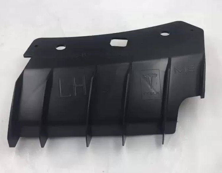
Automotive
| Component | Material | Benefit |
|---|---|---|
| Intake manifolds | Nylon 6/6 with 30% glass | 40% weight reduction; withstands engine temperatures |
| Engine covers | Glass-filled nylon | Heat resistance; aesthetics |
| Transmission components | PEEK, PPS | Wear resistance; high-temperature stability |
| Electrical connectors | PBT, LCP | Electrical properties; dimensional stability |
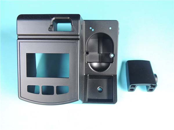
Electronics
| Component | Material | Benefit |
|---|---|---|
| Smartphone housings | PC/ABS blends | Impact resistance; thin-wall capability |
| Connectors | LCP, PBT | Precision; electrical insulation |
| LED components | PC, PEEK | Heat resistance; optical clarity |
| EMI shielding | Conductive plastics | Lightweight; design freedom |
Medical
| Component | Material | Benefit |
|---|---|---|
| Surgical instruments | PEEK, PEI | Biocompatibility; sterilization resistance |
| Drug delivery devices | Medical-grade PC, COC | Precision; chemical resistance |
| Implants | PEEK | Biocompatibility; radiolucency |
| Diagnostic equipment | ABS, PC | Impact resistance; cleanability |
Aerospace
| Component | Material | Benefit |
|---|---|---|
| Interior panels | PEI (Ultem), PPS | Flame retardancy; low smoke; lightweight |
| Fasteners | PEEK | High strength; chemical resistance |
| Electrical components | PEEK, PEI | Thermal stability; insulation |
What Advanced Technologies Are Shaping the Future?
Smart Molding (Industry 4.0)
- Sensors monitor melt pressure, temperature, and flow in real time
- Closed-loop control automatically adjusts parameters to maintain quality
- Data analytics predict maintenance needs and optimize processes
Multi-Material Molding
- Two-shot molding combines rigid and flexible plastics in one cycle
- Insert molding embeds metal components
- Overmolding adds soft-touch surfaces to rigid substrates
Micro Injection Molding
- Produces parts as small as 0.1 grams
- Tolerances to ±0.001 mm
- Applications: micro gears, watch components, medical micro-devices
3D Printing of Molds
- Rapid tooling reduces lead time from weeks to days
- Ideal for prototypes and low-volume production
- Enables complex cooling channels
In-Mold Decoration (IMD)
- Graphics and textures applied during molding
- Eliminates secondary painting or labeling
- Permanent; scratch-resistant finishes
Conclusion
Mastering injection molding of engineering plastics requires a systematic approach across material selection, mold design, process control, and quality assurance.
Key principles:
- Select materials based on mechanical, thermal, and chemical requirements
- Design molds with proper gating, cooling, venting, and wear-resistant steel
- Control parameters—temperature, pressure, speed—within tight tolerances
- Dry materials thoroughly to prevent moisture-related defects
- Implement quality systems with SPC, dimensional inspection, and mechanical testing
When these elements align, engineering plastics deliver components that outperform metal in weight, design freedom, and cost-effectiveness. From automotive underhood to medical implants, these materials enable innovation across industries.
Frequently Asked Questions (FAQ)
What’s the difference between thermoplastics and thermosets in injection molding?
Thermoplastics (ABS, PC, nylon, PEEK) soften when heated and harden when cooled. This process is reversible—they can be remelted and reprocessed. Thermosets (phenolic, epoxy, melamine) undergo chemical curing during molding and cannot be remelted. Thermosets offer superior heat and chemical resistance but cannot be recycled.
How can I reduce cycle time in injection molding?
Cycle time reduction focuses on cooling optimization, which accounts for 50–70% of the cycle. Strategies: use conformal cooling channels that follow part shape; position cooling channels 8–12 mm from cavity; ensure turbulent coolant flow (Reynolds >4,000); reduce mold temperature within material limits; minimize packing time while maintaining part integrity; use hot runner systems to eliminate runner cooling.
Which engineering plastic is best for high-impact applications?
ABS offers excellent impact strength for general applications (20–30 kJ/m² notched Izod). Polycarbonate (PC) provides superior impact resistance (60–80 kJ/m²) with optical clarity—ideal for safety glasses and housings. For extreme conditions, PEEK delivers exceptional impact resistance at high temperatures and in chemically harsh environments.
Why is drying critical for engineering plastics?
Many engineering plastics—nylon, PC, PET, PEEK—are hygroscopic, absorbing moisture from air. During injection, this moisture turns to steam, causing hydrolysis (polymer chain breakdown). Results: voids, surface splay, brittleness, and dramatically reduced mechanical properties. Drying to below 0.02–0.10% moisture (depending on material) prevents these defects and preserves material performance.
What tolerances can be achieved with engineering plastics?
Standard injection molding achieves ±0.1–0.2 mm for general dimensions. Precision molding with well-designed molds and controlled processes achieves ±0.05 mm. Micro injection molding for small components achieves tolerances as tight as ±0.01–0.02 mm. Tight tolerances require precision tooling, stable process control, and materials with consistent shrinkage.
Contact Yigu Technology for Custom Manufacturing
At Yigu Technology, we specialize in injection molding of engineering plastics for demanding applications across automotive, medical, electronics, and aerospace industries. Our expertise spans material selection, precision mold design, process optimization, and quality assurance.
Our engineering plastics capabilities include:
- Material expertise – ABS, PC, nylon, acetal, PEEK, PEI, PPS, and glass/carbon-filled grades
- Precision tooling – H13, P20, and stainless steel molds for high-volume production
- Process optimization – Scientific molding; in-process monitoring; SPC
- Quality assurance – CMM dimensional inspection; mechanical testing; non-destructive testing
- Advanced technologies – Multi-material molding; insert molding; micro molding
We help clients replace metal with lightweight engineering plastics, reduce costs, and achieve superior performance. From prototypes to high-volume production, we deliver components that meet the most demanding specifications.
Contact us today to discuss your engineering plastics injection molding project. Let our expertise help you achieve reliable, high-quality results.