Introduction
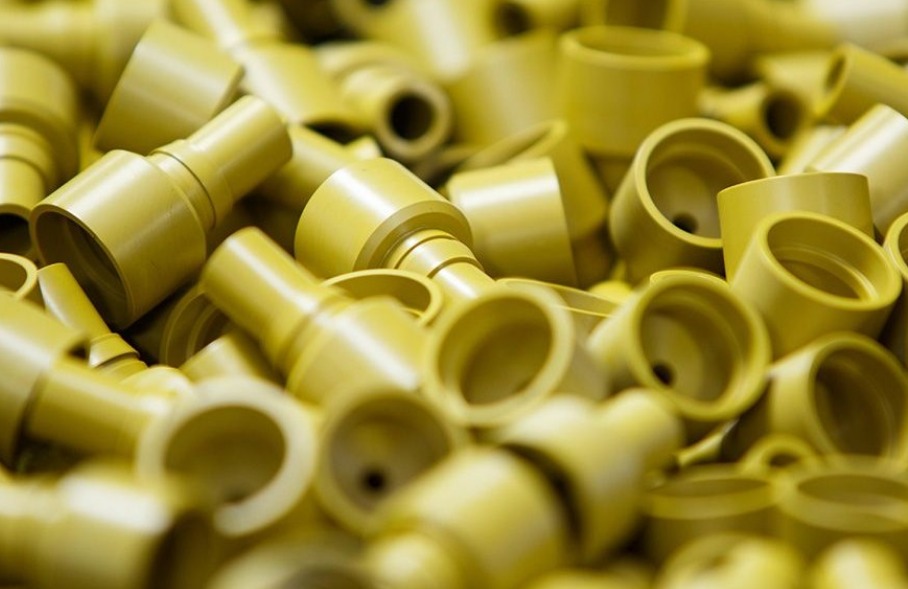
Injection molding is everywhere. It produces the plastic parts that surround us—from smartphone cases to automotive dashboards. But behind the simplicity of a finished plastic part lies a complex process with many variables.
Temperatures must be precise. Pressures must be controlled. Cooling times must be optimized. Get any of these wrong, and defects appear: warping, sink marks, short shots, flash. The challenge? Managing all these variables while maintaining efficiency and quality.
At Yigu Technology, we’ve spent years simplifying injection molding for our clients. In this guide, we’ll break the process into clear, actionable steps—from material selection to production monitoring. Whether you’re new to injection molding or looking to optimize existing operations, this step-by-step approach will help you produce better parts, faster.
Why Is Simplifying Injection Molding Important?
Injection molding involves multiple interdependent parameters. A change in one affects others. For example, raising melt temperature improves flow but may increase cooling time and risk of degradation.
When the process is overly complex or poorly understood, manufacturers face:
- Defects: Warping, sink marks, short shots, flash
- Inefficiency: Long cycle times, excessive scrap
- Cost overruns: Wasted material, rework, downtime
Simplifying the process doesn’t mean ignoring complexity. It means understanding the key levers and controlling them systematically. The result: consistent quality, shorter cycles, and lower costs.
The global injection molding market was valued at over $300 billion in 2023 and continues to grow. Manufacturers who master process simplification gain a significant competitive advantage.
Step 1: Select the Right Material
Material selection is the foundation of successful injection molding. The wrong material leads to field failures, processing difficulties, or unnecessary cost.
Key Material Properties to Consider
| Property | Why It Matters |
|---|---|
| Melt flow index | Affects how easily the material fills the mold |
| Heat deflection temperature | Determines maximum operating temperature |
| Impact resistance | Critical for parts subject to drops or impacts |
| Chemical resistance | Important for applications exposed to fuels, solvents, or cleaning agents |
| Shrinkage | Affects dimensional accuracy; must be compensated in mold design |
Common Materials and Their Applications
| Material | Characteristics | Typical Applications |
|---|---|---|
| Polypropylene (PP) | Lightweight, chemical resistance, heat resistance to 100–120°C, low cost | Food containers, automotive interior parts, living hinges |
| Polyethylene (PE) | Good electrical insulation, low cost, various densities | Packaging, bottles, toys, pipes |
| Polystyrene (PS) | Transparent, easy to process, brittle | Disposable cutlery, packaging, model making |
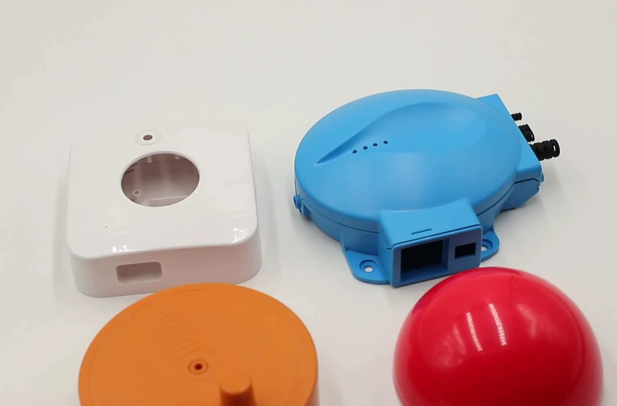
| Polycarbonate (PC) | High impact resistance, transparent, heat resistance to 130–140°C | Electronics housings, automotive lighting, safety equipment |
| ABS | Good impact resistance, good surface finish, dimensional stability | Electronics housings, toys, automotive interior parts |
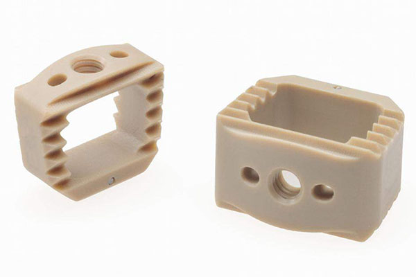
Pro tip: For high-temperature applications (e.g., under-hood automotive), consider engineering plastics like PEEK (continuous use to 260°C) or nylon. For food contact, ensure the material meets FDA or EU food-grade standards.
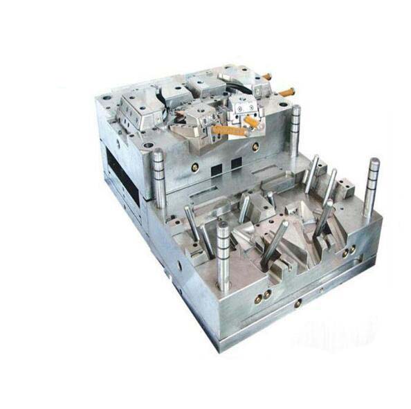
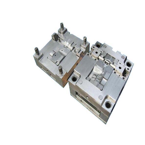
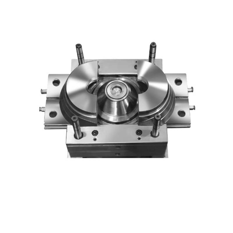
Step 2: Design the Mold for Manufacturability
The mold is where the part takes shape. A well-designed mold simplifies the entire process. A poorly designed mold creates problems that no amount of process tuning can fix.
Runner Design
The runner system carries molten plastic from the nozzle to the cavities. A balanced runner system ensures all cavities fill simultaneously and uniformly.
- Unbalanced runners: Cause some cavities to fill before others, leading to inconsistent parts
- Balanced runners: Distribute pressure and flow evenly, reducing short shots and defects
Example: In a multi-cavity mold for circular parts, a fan-shaped runner distributes material evenly to each cavity—preventing some parts from filling while others remain incomplete.
Gate Placement
The gate is where plastic enters the cavity. Gate location affects:
- Flow pattern: Poor placement causes weld lines or flow marks
- Part appearance: Gates leave marks; place them in non-cosmetic areas
- Stress concentration: Gates near thin sections can cause cracking
Cooling System
Cooling accounts for 70–80% of cycle time. Efficient cooling is essential for both productivity and part quality.
Guidelines:
- Place cooling channels 1.5–2 times their diameter from the cavity surface
- Use conformal cooling for complex parts—channels that follow the part contour cool more evenly than straight-drilled channels
- Ensure uniform cooling across the part to prevent warpage
Example: A complex automotive part with varying wall thickness required conformal cooling channels to eliminate hot spots. Cycle time dropped by 25% , and warpage was eliminated.
Step 3: Calibrate the Machine Precisely
Even with the right material and mold, poor machine settings cause defects. Calibration involves setting temperature, pressure, and speed parameters within the material’s processing window.
Temperature Control
Each material has a specific processing temperature range. Staying within this range is critical.
| Material | Processing Temperature Range |
|---|---|
| Polypropylene | 200–250°C |
| ABS | 200–250°C |
| Polycarbonate | 260–300°C |
| Nylon | 240–290°C |
Effects of temperature deviation:
- Too low: Poor flow, short shots, surface defects
- Too high: Material degradation, discoloration, reduced mechanical properties
Pressure and Speed Settings
| Parameter | Typical Range | Impact |
|---|---|---|
| Injection pressure | 50–200 MPa | Filling ability, part density |
| Injection speed | 10–200 mm/s | Surface finish, internal stress, air entrapment |
| Packing pressure | 50–80% of injection | Compensates for shrinkage, prevents sink marks |
| Back pressure | 5–20 MPa | Melt homogeneity, additive mixing |
Rule of thumb:
- Start with the material supplier’s recommended settings
- Run a design of experiments (DOE) to optimize for your specific part
- Document successful settings for repeatability
Example: A thin-walled electronics housing required high injection speed (120 mm/s) to fill before freezing, but this caused air entrapment. Reducing speed to 90 mm/s and adding vents eliminated bubbles while maintaining fill.
Step 4: Monitor the Process in Real Time
Process monitoring transforms injection molding from guesswork to science. Sensors and software provide visibility into what’s happening inside the mold—cycle by cycle.
Key Sensors
| Sensor Type | Monitors | Detects |
|---|---|---|
| Cavity pressure | Pressure during filling and packing | Blockages, improper filling, inconsistent packing |
| Melt temperature | Temperature at nozzle or in cavity | Temperature drift, degradation risk |
| Mold temperature | Temperature distribution in mold | Uneven cooling, cooling system issues |
| Screw position | Shot size consistency | Material variation, screw wear |
Monitoring Software
Advanced monitoring software collects data from multiple sensors, displays real-time parameters, and generates reports. Some systems use machine learning to predict problems before they occur.
Example: A gradual increase in injection pressure over several cycles often indicates a clogged runner or degraded material. Monitoring software alerts operators to clean the runner or change material—before defective parts are produced.
Benefits:
- Detect issues early, reducing scrap
- Maintain consistent quality across shifts
- Provide traceability for regulated industries (medical, automotive)
Step 5: Implement Preventive Maintenance
A well-maintained machine runs consistently. A neglected machine produces unpredictable results.
Maintenance Schedule
| Component | Frequency | Actions |
|---|---|---|
| Mold | Every 10,000–50,000 cycles | Clean, inspect for wear, check vents, lubricate moving parts |
| Screw and barrel | Annually or per material change | Inspect for wear, clean, check heating bands |
| Hydraulic system | Monthly | Check fluid levels, inspect hoses for leaks, change filters |
| Cooling system | Weekly | Check flow rates, clean cooling channels |
Proactive maintenance reduces unplanned downtime—which can cost $1,000–$5,000 per hour in lost production, depending on the operation.
How Does Yigu Technology Simplify Injection Molding?
At Yigu Technology, we’ve built our reputation on making injection molding simpler for our clients—without compromising quality.
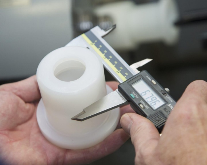
Material expertise: We help clients select the right material for their application, balancing performance, cost, and processability. For high-precision parts, we evaluate dimensional stability and shrinkage characteristics to ensure the final part meets specifications.
Optimized mold design: Our team uses mold flow analysis to predict filling, cooling, and warpage before tooling begins. We design runners, gates, and cooling channels to minimize defects and cycle time. Simpler molds with fewer components are easier to maintain and less prone to failure.
Process calibration: We document optimal settings for every project—temperature, pressure, speed, cooling time. This ensures repeatability across production runs and shifts.
Real-time monitoring: Our production floor uses cavity pressure sensors and monitoring software to track every cycle. When parameters drift, operators are alerted immediately—preventing defective parts.
Continuous improvement: We treat every project as an opportunity to refine our process. Data from monitoring systems feeds back into mold design and process settings, driving ongoing improvements.
Case example: A client producing medical device housings struggled with inconsistent dimensions—parts were out of tolerance 5% of the time. We reviewed their process, identified that cooling was uneven, and modified the mold with conformal cooling channels. Cycle time dropped by 15%, and dimensional consistency improved to 99.8% within spec.
Conclusion
Injection molding doesn’t have to be complex. By following a systematic approach, you can simplify the process and achieve consistent, high-quality results:
- Select the right material for your application
- Design the mold with balanced runners, proper gates, and efficient cooling
- Calibrate the machine with precise temperature, pressure, and speed settings
- Monitor the process in real time to catch issues early
- Maintain equipment proactively to prevent unplanned downtime
Each step builds on the previous. Skip one, and complexity returns. Master them all, and injection molding becomes a reliable, predictable manufacturing method—delivering quality parts on time, every time.
FAQ
What are the common problems in injection molding and how to solve them?
| Defect | Cause | Solution |
|---|---|---|
| Flash | Insufficient clamping force; worn mold; excessive injection pressure | Increase clamping force; repair or replace mold components; reduce injection pressure |
| Sink marks | Uneven cooling; insufficient packing pressure | Optimize cooling system; increase packing pressure/time; reduce thick wall sections |
| Short shots | Low injection pressure; poor flow; inadequate venting | Increase injection pressure; enlarge runner/gate; improve venting |
| Warpage | Uneven cooling; differential shrinkage | Add cooling channels; balance wall thickness; use lower mold temperature |
| Burn marks | Trapped air; excessive injection speed | Improve venting; reduce injection speed |
How to choose the right injection molding machine?
Three factors determine machine selection:
Clamping force: Calculate based on projected area × cavity pressure. Formula: (F = P \times A). Add a 1.17 safety factor. Example: Part with 100 cm² projected area, cavity pressure 400 kg/cm² → required force 40,000 kg → machine should provide at least 47,000 kg (47 tons).
Injection volume: Machine injection volume should be 1.35 times the total shot volume (part + runner). For a 100 cm³ shot, choose machine with at least 135 cm³ capacity.
Screw diameter: Larger screws handle high-volume, low-viscosity materials. Smaller screws provide higher pressure for viscous materials or complex parts.
Can injection molding be used for all types of plastics?
No. Thermoplastics (PP, PE, PS, PC, ABS, nylon, etc.) are suitable—they can be melted, injected, cooled, and remelted. Thermosets (phenolic, epoxy, etc.) cure chemically during processing and cannot be remelted. While some thermosets are injection molded, they require specialized equipment and processes. For standard injection molding, thermoplastics are the primary materials.
What is the most important parameter in injection molding?
There’s no single “most important” parameter—they’re interdependent. However, temperature has the widest impact. Melt temperature affects flow, cooling time, and material properties. Mold temperature affects cooling rate, surface finish, and internal stresses. Improper temperature control can’t be compensated by adjusting other parameters. Start with correct temperatures, then optimize pressure and speed.
How can I reduce injection molding cycle time?
Cycle time is dominated by cooling (70–80% of total). Focus on:
- Optimize cooling: Use conformal cooling channels; place channels close to cavity surface
- Reduce wall thickness: Redesign thick sections with ribs for stiffness
- Increase mold temperature: Paradoxically, higher mold temperatures can sometimes reduce cycle time by improving heat transfer (depends on material)
- Automate: Reduce manual handling time with robots
- Use hot runners: Eliminate runner cooling and trimming time
Contact Yigu Technology for Custom Manufacturing
Ready to simplify your injection molding process? At Yigu Technology, we combine material expertise, precision mold design, and advanced process monitoring to deliver high-quality custom plastic parts—efficiently and reliably.
From material selection to production optimization, our team is committed to making injection molding simpler for you. Contact us today to discuss your project and discover how our step-by-step approach can improve your quality, reduce costs, and accelerate your time to market.