Introduction
Aluminum is everywhere in modern engineering. You will find it in aircraft wings, electric car frames, robot arms, and even your smartphone chassis. But here is the thing — aluminum only performs when it is machined right. Pick the wrong alloy, and your part warps. Ignore thermal distortion, and your tolerances blow out. Skip design for manufacturability, and you waste weeks on redesigns.
This guide breaks down exactly why aluminum CNC machining is the go-to process for precision parts. We cover alloy selection, thermal management, surface finish, cost control, and post-machining treatments. Whether you are a mechanical engineer designing a new product or a procurement lead sourcing a machining partner, this article gives you the playbook you need.
1. What Is Aluminum CNC Machining?
The Basics of CNC Milling and Turning
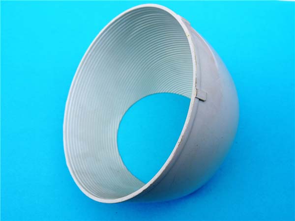
Aluminum CNC machining uses computer-controlled tools to cut raw aluminum stock into precise shapes. The two main processes are CNC milling (rotating cutters remove material) and CNC turning (a lathe spins the part while a tool cuts it). Both rely on G-code programs that control every axis of motion.
The result? Parts with tolerances as tight as ±0.005 mm. Repeatability across thousands of units. And surface finishes that meet aerospace-grade specs.
Why Engineers Choose Aluminum
Aluminum earns its spot in nearly every industry for good reasons:
| Property | Benefit for Machining |
|---|---|
| Low density (2.7 g/cm³) | Lightweight parts without sacrificing strength |
| High thermal conductivity | Heat dissipates fast — but this also creates challenges |
| Excellent machinability | Cuts cleanly with less tool wear than steel |
| Natural corrosion resistance | Less post-processing needed in many environments |
| Recyclable | Meets sustainability goals without cost penalty |
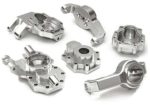
Common applications include aerospace structural brackets, automotive engine blocks, medical device housings, robotic end-effectors, and consumer electronics enclosures. In short, if you need a strong, light, and precise part — aluminum is the default choice.
2. How to Select the Right Aluminum Alloy
Alloy Families at a Glance
Not all aluminum is the same. The alloy you pick determines strength, machinability, corrosion resistance, and cost. Here is a quick breakdown:
| Alloy Series | Key Alloys | Best For | Machinability Rating |
|---|---|---|---|
| 6xxx (6061, 6063) | 6061-T6, 6063-T5 | General purpose, structural, anodizing | ★★★★★ Excellent |
| 7xxx (7075, 7050) | 7075-T6, 7050-T7451 | High-strength aerospace, tooling | ★★★☆☆ Fair |
| 2xxx (2024, 2014) | 2024-T3, 2014-T6 | Aircraft skins, fatigue-critical parts | ★★★☆☆ Fair |
| 5xxx (5052, 5083) | 5052-H32, 5083-H116 | Marine, welded structures | ★★★★☆ Very Good |
Matching Alloy to Your Needs
Here is how to think about it in practice:
- Need to anodize? Go with 6061 or 6063. These alloys produce uniform, beautiful anodized finishes. 7075 anodizes unevenly and looks patchy.
- Need max strength? Pick 7075-T6. It rivals some steels in tensile strength (up to 572 MPa). But expect faster tool wear and higher machining costs.
- Need weldability? Choose 5052 or 5083. The 6xxx and 7xxx series weld poorly due to hot cracking risks.
- Need fatigue resistance? 2024-T3 is the aerospace standard for cyclic loading.
Pro Tip from the Shop Floor: At our facility, we see 6061-T6 used in about 60% of all aluminum CNC jobs. It hits the sweet spot of strength, machinability, and cost. Only go to 7075 when you truly need that extra 40% strength — and budget for 20–30% higher tooling costs.
Decision Matrix: Machinability vs. Performance
| Priority | Recommended Alloy | Why |
|---|---|---|
| Fast machining, low cost | 6061-T6 | Easy to cut, great surface finish |
| Maximum strength | 7075-T6 | 572 MPa tensile, but harder on tools |
| Best anodizing result | 6063-T5 | Uniform oxide layer, consistent color |
| Marine / saltwater | 5083-H116 | Superior corrosion resistance in saltwater |
| Fatigue-critical aerospace | 2024-T3 | Proven in aircraft for decades |
3. Solving the Thermal Distortion Problem
Why Aluminum Warps During Machining
Here is a fact that trips up even experienced engineers: aluminum conducts heat 3x faster than steel. That sounds like a good thing — until you realize the heat concentrates right at the cutting zone. The result? Thermal expansion during the cut, then shrinkage after the part cools. Your 50 mm feature becomes 49.97 mm. Tight tolerances? Gone.
This is the #1 reason aluminum parts fail inspection.
Machining Strategies That Work
| Strategy | How It Helps |
|---|---|
| Use flood coolant or MQL | Removes heat at the source before it spreads |
| Climb milling over conventional | Reduces heat buildup by 15–25% |
| Light roughing passes, heavy finishing | Removes bulk material gently, then cuts to final size |
| High-speed machining (HSM) | Shorter chip contact time = less heat per cut |
| Stress-relieve before finish cuts | Let the part sit or run a light skim pass to stabilize |
Real-World Example: A robotics client sent us a 7075 bracket with ±0.02 mm tolerance. First run: 40% reject rate due to warping. We switched to climb milling with mist coolant and added a 30-minute stress-relief hold before the final pass. Reject rate dropped to under 2%. Same machine. Same tool. Just smarter process control.
Fixture Design Matters
Poor fixturing causes distortion too. If you clamp a thin aluminum part too hard, you introduce residual stress that releases later. Best practices:
- Use soft jaw fixtures or vacuum tables
- Distribute clamping force across a wide area
- Avoid clamping near thin walls or fine features
- Let the part "breathe" — do not over-constrain it
4. Achieving Precision Surface Finish
Tooling Choices for Aluminum
The right tool makes or breaks your surface finish. Here is what works:
| Tool Type | Best For | Recommended Coating |
|---|---|---|
| Carbide end mills (3-flute) | General milling, good chip evacuation | TiAlN or DLC |
| Carbide end mills (4-flute) | Fine finish, tight tolerance walls | Uncoated or ZrN |
| HSS tools | Low-speed work, prototyping | None needed |
| Diamond-coated tools | Mirror finish, non-ferrous only | Diamond (obviously) |
Speeds and Feeds for Surface Quality
Getting the right speeds and feeds is not optional. Too slow, and you rub instead of cut — leaving burrs and poor finish. Too fast, and you get chatter marks.
| Operation | RPM Range (10mm carbide tool) | Feed Rate | Goal |
|---|---|---|---|
| Roughing 6061 | 8,000–12,000 | 800–1,200 mm/min | Fast material removal |
| Finishing 6061 | 12,000–18,000 | 400–600 mm/min | Ra 0.8 µm or better |
| Roughing 7075 | 6,000–9,000 | 600–900 mm/min | Control heat, reduce tool wear |
| Finishing 7075 | 10,000–14,000 | 300–500 mm/min | Ra 1.6 µm typical |
When to Add Post-Machining
Sometimes as-machined is not enough. Here is when to specify extra steps:
- Ra < 0.8 µm needed? Add precision grinding or lapping
- Uniform matte look? Specify bead blasting (120–200 grit)
- Mirror finish? Go with mechanical polishing + anodizing
- Cosmetic edges? Request chamfering or deburring as a separate op
5. Cost Control From Prototype to Production
Where Aluminum Machining Costs Come From
Most engineers underestimate machining cost because they only see the per-hour rate. The real cost drivers are:
| Cost Factor | Impact on Price | How to Reduce It |
|---|---|---|
| Material waste | 15–25% of total cost | Optimize nesting, use near-net shapes |
| Tool wear | 5–15% per part (hard alloys) | Choose machinable alloys, use coatings |
| Setup time | High for small batches | Design for fewer setups, use modular fixtures |
| Machine time | The biggest variable | Optimize tool paths, use HSM strategies |
| Inspection/rework | Can double cost if tolerances are tight | Get DFM right the first time |
Batch Size Economics
| Batch Size | Typical Cost Per Part | Strategy |
|---|---|---|
| 1–10 pcs (prototype) | 50–500+ | Use 6061, loose tolerances, 3-axis only |
| 10–100 pcs (bridge run) | 20–150 | Tighten tolerances, add 4th axis if needed |
| 100–1,000 pcs (production) | 5–80 | Amortize setup, use dedicated tooling |
| 1,000+ pcs (high volume) | 2–40 | Consider transfer lines or swiss machining |
Cost-Saving Insight: A client redesigned a 6061 housing to add 0.5 mm radius corners instead of 0.2 mm. Same function. But machining time dropped 35% because the tool could move faster without dwell. Savings: 12perpartat500−unitvolume.Thatis6,000 saved on one design change.
6. Design for Manufacturability Rules
Critical DFM Rules for Aluminum
Your CAD model looks perfect on screen. But the machine does not care about your render. Follow these rules to avoid costly redesigns:
| DFM Rule | Minimum Value | Why It Matters |
|---|---|---|
| Wall thickness | ≥ 1.5 mm (6061), ≥ 2.0 mm (7075) | Thin walls vibrate and chatter |
| Internal corner radius | ≥ 0.5 mm | Tools cannot cut sharp internal corners |
| Hole depth-to-diameter | ≤ 5:1 (standard), ≤ 10:1 (gun drill) | Deep holes break tools without proper support |
| Tolerance on deep pockets | ±0.1 mm minimum | Tighter tolerances cost 3–5x more |
| Text height for engraving | ≥ 0.3 mm | Smaller text blurs during machining |
Tolerance Stacking Reality Check
Every tolerance you add stacks up. A part with 10 tight tolerances is almost guaranteed to fail inspection. Here is a better approach:
- Identify critical-to-function (CTF) dimensions — tight tolerance only here
- Use loose tolerances (±0.2 mm or more) on non-critical features
- Apply GD&T properly — use positional tolerancing instead of linear stacks
- Talk to your machinist early — they will tell you what is realistic
Engineer-to-Machinist Tip: We always tell clients: "Send us your CAD file before you finalize it." We catch DFM issues in 24 hours that would cost weeks to fix after tooling is ordered.
7. Post-Machining Treatments
Anodizing: Alloy Matters More Than You Think
Anodizing is the most common finish for aluminum CNC parts. But not all alloys anodize the same way.
| Alloy | Anodizing Quality | Color Consistency | Notes |
|---|---|---|---|
| 6061-T6 | Excellent | Very consistent | Industry standard for anodizing |
| 6063-T5 | Excellent | Best of all | Preferred for architectural/cosmetic parts |
| 7075-T6 | Fair | Inconsistent, streaky | Copper content causes uneven oxide |
| 2024-T3 | Poor | Very poor | High copper — almost never anodized |
| 5052-H32 | Good | Good | Works well for marine applications |
If you need a black anodized finish on 7075, expect it to look dark gray with patches. Budget for extra quality checks.
Coating and Corrosion Protection Options
| Treatment | Best Alloy Match | Thickness | Use Case |
|---|---|---|---|
| Chem film (Alodine) | All alloys | 0.5–1.5 µm | Military spec, paint prep |
| Powder coating | 6061, 5052 | 50–100 µm | Outdoor, colorful finishes |
| Liquid paint | All alloys | 25–75 µm | Complex shapes, masking needed |
| Hard anodize (Type III) | 6061, 6063 | 25–50 µm | Wear-resistant, military/industrial |
Design Note: If you specify powder coating, tell your machinist the target thickness. A 75 µm coating on a tight-tolerance shaft means you need to machine undersize by that amount. We see this mistake at least once a month — and it always costs money.
Conclusion
Aluminum CNC machining is not just a manufacturing process — it is a strategic engineering decision. The right alloy, the right process parameters, and the right DFM choices can mean the difference between a part that performs flawlessly and one that fails in the field.
To recap the key takeaways:
- 6061-T6 is your workhorse — use it unless you have a specific reason not to
- Control heat or lose tolerances — use climb milling, proper coolant, and stress relief
- Design for the machine — not just for the CAD screen
- Pick your finish early — alloy choice and anodizing are linked from day one
- Talk to your machinist — the best designs come from collaboration, not isolation
Master these principles, and you will get precision aluminum parts that meet spec, stay on budget, and ship on time. Every single time.
FAQ
What is the best aluminum alloy for CNC machining?
6061-T6 is the best all-around choice. It machines easily, anodizes well, and offers good strength at a low cost. Use 7075-T6 only when you need maximum strength.
Does aluminum warp during CNC machining?
Yes. Aluminum's high thermal conductivity causes heat buildup at the cut zone. This leads to thermal distortion and warping. Use climb milling, flood coolant, and stress-relief techniques to minimize it.
What surface finish can you achieve on aluminum CNC parts?
With proper tooling and parameters, you can reach Ra 0.8 µm or better directly from the machine. For mirror finishes (Ra 0.2 µm), add polishing or diamond turning as a post-process.
How much does aluminum CNC machining cost?
Prototype parts (1–10 pcs) range from 50to500+ each. Production runs (100+ pcs) can drop to 5–80 per part depending on complexity, alloy, and tolerances.
Can you anodize 7075 aluminum?
Technically yes, but the results are inconsistent. 7075 contains copper, which causes streaky, uneven anodizing. For a quality anodized finish, stick with 6061 or 6063.
What tolerances are realistic for aluminum CNC machining?
Standard CNC machining achieves ±0.05 mm (±0.002"). Tight tolerance machining can reach ±0.005 mm (±0.0002") but at significantly higher cost.
What DFM rules should I follow for aluminum parts?
Keep wall thickness ≥1.5 mm, internal radii ≥0.5 mm, and hole depth-to-diameter ratios under 5:1 for standard tools. Always apply GD&T instead of tight linear tolerances.
Contact Yigu Technology for Custom Manufacturing
Need precision aluminum CNC machined parts done right the first time? Yigu Technology specializes in custom CNC machining for prototypes and production runs. From alloy selection to anodizing, we handle the full process under one roof.
📞 Get a quote today — upload your CAD file and receive a DFM review within 24 hours.