Introduction
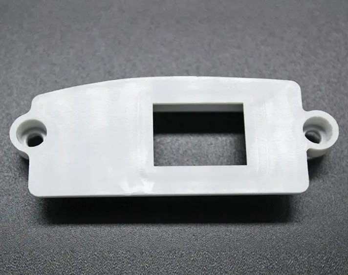
PEEK GF30 is not ordinary plastic. The 30% glass fiber reinforcement doubles its tensile strength compared to unreinforced PEEK. It offers exceptional rigidity, thermal stability up to 260°C, and wear resistance that outperforms many metals. Engineers choose it for aerospace brackets, automotive transmission components, and semiconductor equipment that must perform reliably in demanding environments.
But machining PEEK GF30 is not simple. The glass fibers make it highly abrasive. Tool wear accelerates. The heterogeneous structure causes uneven cutting forces. Fiber pull-out and matrix cracking risk surface defects. And the anisotropic properties—fibers align during extrusion—create variations in machinability across different axes.
This guide addresses these challenges. You will learn about material properties, machining techniques, tool selection, and quality control. By the end, you will have a clear strategy for CNC machining PEEK GF30 components that meet the tightest specifications.
What Makes PEEK GF30 a High-Performance Material?
Material Properties
PEEK GF30 combines the benefits of PEEK with enhanced properties from 30% glass fiber reinforcement.
| Property | PEEK GF30 | Unreinforced PEEK | Significance |
|---|---|---|---|
| Tensile strength | 170–190 MPa | 90–100 MPa | Nearly double; high-load capacity |
| Flexural modulus | 15–17 GPa | 3.6 GPa | Exceptional rigidity |
| Thermal expansion | 20–25 μm/m·K | 45–50 μm/m·K | 50% lower; dimensional stability |
| Continuous use temp | Up to 260°C | Up to 260°C | Maintains properties at high temperatures |
| Creep | 70% lower than PEEK | Baseline | Maintains shape under prolonged stress |
| Abrasion resistance | Very good | Good | 40% improvement; ideal for sliding components |
Key Characteristics
Mechanical strength – Tensile strength of 170–190 MPa (nearly double unreinforced PEEK) and flexural modulus of 15–17 GPa provide exceptional load-bearing capacity for high-load applications.
High rigidity and dimensional stability – Glass fibers reduce creep by 70% compared to unreinforced PEEK. Parts maintain shape under prolonged stress—critical for aerospace and industrial machinery.
Thermal stability – Retains properties at continuous use temperatures up to 260°C . Thermal expansion rate is 50% lower than standard PEEK, minimizing post-machining dimensional changes.
Chemical resistance – Good resistance to oils, fuels, and most industrial solvents. Concentrated acids can degrade the polymer matrix over time.
Wear resistance – Glass fiber reinforcement reduces friction and improves abrasion resistance by 40% compared to unreinforced PEEK. Suitable for sliding components like bearings.
Anisotropic properties – Fibers align along the extrusion direction. Machining is easier parallel to the fiber axis but more challenging perpendicular to it. Parameters must be adjusted for each orientation.
What Are the Machining Challenges?
| Challenge | Cause | Consequence |
|---|---|---|
| Rapid tool wear | Abrasive glass fibers | 3–4× faster wear than unreinforced PEEK; increased tooling costs |
| Fiber pull-out | Uneven cutting forces | Surface defects; rough finish; potential failure points |
| Matrix cracking | Improper parameters | Structural weakness; part rejection |
| Directional variations | Fiber alignment | Machinability differs across axes; inconsistent results |
| Heat generation | Friction from fibers | Resin softening; dimensional inaccuracies |
| Chip management | Glass fiber chips | Abrasive chips damage tools and surfaces |
What Machining Techniques Work Best?
Milling
Milling is the primary operation for PEEK GF30. Use ultra-hard tools and controlled parameters.
| Parameter | Recommendation |
|---|---|
| Spindle speed | 6000–10,000 RPM |
| Feed rate | 0.05–0.1 mm/tooth |
| Depth of cut | 0.3–1.0 mm (roughing); 0.1–0.2 mm (finishing) |
| Tolerance capability | ±0.015 mm with precision setups |
Climb milling is preferred over conventional milling. It reduces fiber pull-out by shearing fibers cleanly. Conventional milling increases the risk of fiber detachment, leaving rough surfaces.
Turning
Suitable for cylindrical PEEK GF30 parts like shafts and bushings.
| Parameter | Recommendation |
|---|---|
| Spindle speed | 2000–4000 RPM |
| Feed rate | 0.08–0.15 mm/rev |
| Tool geometry | Negative rake angles (-5° to -10°) |
Negative rake angles reduce fiber pull-out, ensuring smooth surfaces. Sharp tools with proper geometry are essential.
Drilling and Threading
| Operation | Recommendation |
|---|---|
| Drill | Carbide drills; 140° point angle; parabolic flutes for chip evacuation |
| Threading | Forming taps (instead of cutting taps) to prevent fiber damage |
| Speed | 500–1000 RPM for threading |
Cutting Parameter Optimization
| Strategy | Benefit |
|---|---|
| Lower feed rate (0.05–0.08 mm/tooth) | Minimizes tool engagement with glass fibers; reduces abrasion |
| Shallower depth of cut (0.3–1 mm) | Reduces cutting forces; prevents fiber pull-out |
| Coolant (5–10% water-soluble emulsion) | Directs coolant to cutting zone; dissipates heat; flushes abrasive chips |
Fiber Orientation Considerations
| Orientation | Machining Characteristic | Parameter Adjustment |
|---|---|---|
| Parallel to fibers | Easier; smoother cuts; less wear | Standard parameters |
| Perpendicular to fibers | More difficult; higher risk of pull-out | Slower feed rates (0.05 mm/tooth vs. 0.08 mm/tooth); sharper tools |
What Tooling Is Required?
Cutting Tools
| Tool Type | Recommendation | Benefit |
|---|---|---|
| Diamond-coated carbide | High-volume production | Resists abrasion; extends tool life |
| PCD (polycrystalline diamond) | Precision work, high-volume | Maximum wear resistance; best surface finish |
| Carbide | General machining | Good balance; requires more frequent replacement |
Tool Geometry
| Feature | Recommendation |
|---|---|
| Rake angle | Negative (-5° to -10°) for turning; positive for milling with proper clearance |
| Cutting edge | Sharp; honed to resist chipping |
| Helix angle | 30–35° for end mills; balances cutting efficiency and chip evacuation |
Tool Life Expectancy
| Tool Type | Expected Life (vs. Unreinforced PEEK) |
|---|---|
| Uncoated carbide | 25–30% of life machining unreinforced PEEK |
| Diamond-coated carbide | 60–70% of life machining unreinforced PEEK |
| PCD | 80–90% of life machining unreinforced PEEK |
Coolant Systems
| Feature | Requirement |
|---|---|
| Pressure | 30–50 bar (high-pressure) |
| Filtration | 5–10 μm to remove glass fiber chips |
| Coolant type | Water-soluble emulsion (5–10% concentration) |
Workholding
| Method | Best For |
|---|---|
| Vacuum fixtures | Thin-walled parts; prevents distortion |
| Soft jaws | Round parts; distributes clamping force |
| Custom fixtures | Complex geometries; even support |
What Surface Finish and Quality Can You Achieve?
Surface Finish Targets
| Application | Target Ra |
|---|---|
| Standard machining | 1.6–3.2 μm |
| Sealing surfaces | <2.0 μm |
| Precision components | <1.6 μm (with PCD tools, optimized parameters) |
Improving Surface Finish
| Strategy | Effect |
|---|---|
| PCD tools | Cleaner cuts; less fiber pull-out |
| Reduced feed rate (0.03–0.05 mm/tooth) | Finer surface |
| Light finishing pass (0.1–0.2 mm depth) | Removes surface irregularities |
| High spindle speed (10,000–12,000 RPM) | Minimizes fiber damage |
Quality Control
| Method | Purpose |
|---|---|
| CMM (Coordinate Measuring Machine) | Dimensional verification; high-resolution probes (0.1 μm); measure at 23°C ±1°C to account for thermal expansion |
| Profilometer | Surface roughness measurement; diamond tips detect fiber pull-out |
| SPC (Statistical Process Control) | Tracks dimensional variations across production runs |
| Ultrasonic testing | Detects subsurface defects (delamination, voids) |
| Hardness testing (Shore D) | Verifies glass fiber distribution uniformity (target 90–95) |
Tolerance Capability
| Application | Achievable Tolerance |
|---|---|
| Standard parts | ±0.02–0.05 mm |
| Aerospace components | ±0.01–0.02 mm |
| Precision features | ±0.015 mm with optimized setups |
In-Process Monitoring
Real-time vibration sensors and cutting force analyzers detect tool wear early. This reduces scrap rates by up to 30% by preventing defects before they occur.
Where Is PEEK GF30 Used?
Aerospace Components
| Component | Property Leveraged |
|---|---|
| Structural brackets | High rigidity, thermal stability |
| Valve bodies | Chemical resistance, strength |
| Engine sensors | Thermal stability up to 260°C |
Automotive Parts
| Component | Property Leveraged |
|---|---|
| Transmission components | Mechanical strength, oil/fuel resistance |
| Turbocharger housings | Thermal stability, rigidity |
| Under-hood brackets | High-load capacity, durability |
Industrial Machinery
| Component | Property Leveraged |
|---|---|
| Gear teeth | Wear resistance, low creep |
| Bearing races | Abrasion resistance, dimensional stability |
| Pump impellers | Chemical resistance, strength |
Medical Implants
| Component | Property Leveraged |
|---|---|
| Orthopedic spacers | Biocompatibility; mechanical similarity to bone |
| Surgical instrument components | Sterilizable, strength |
| Note | Fiber leaching must be controlled |
Semiconductor Equipment
| Component | Property Leveraged |
|---|---|
| Wafer handling arms | Low outgassing, dimensional stability |
| Chamber fixtures | Thermal stability, cleanliness |
High-Temperature Applications
| Component | Property Leveraged |
|---|---|
| Oven components | Continuous exposure to 200–260°C |
| Heat exchanger parts | Thermal stability, corrosion resistance |
| Furnace fixtures | Outperforms many metals in corrosion resistance |
Conclusion
PEEK GF30 delivers exceptional performance where strength, rigidity, and thermal stability are required. Its tensile strength of 170–190 MPa and flexural modulus of 15–17 GPa provide load-bearing capacity that nearly doubles unreinforced PEEK. Its thermal expansion rate is 50% lower , ensuring dimensional stability at continuous use temperatures up to 260°C.
But machining PEEK GF30 requires specialized expertise. The glass fibers are highly abrasive—tool wear is 3–4 times faster than with unreinforced PEEK. Use diamond-coated carbide or PCD tools to resist abrasion. Apply negative rake angles (-5° to -10°) for turning to reduce fiber pull-out. Use climb milling to shear fibers cleanly.
Optimize parameters for fiber orientation. Machining parallel to fibers is easier. Perpendicular cutting requires slower feed rates (0.05 mm/tooth vs. 0.08 mm/tooth) and sharper tools. Apply high-pressure coolant (30–50 bar) with 5–10 μm filtration to flush abrasive chips and dissipate heat.
Surface finishes of Ra <1.6 μm are achievable with PCD tools, reduced feed rates, and light finishing passes. Quality control includes CMM inspection at controlled temperatures (23°C ±1°C), profilometer measurement, and ultrasonic testing for subsurface defects. In-process monitoring reduces scrap rates by up to 30%.
From aerospace brackets to semiconductor equipment, from automotive transmission components to high-temperature industrial parts, PEEK GF30 delivers performance that justifies the machining investment. With the right techniques, tools, and quality control, you can produce components that meet the most demanding specifications.
FAQ
Why is PEEK GF30 more difficult to machine than unreinforced PEEK?
PEEK GF30’s 30% glass fibers make it highly abrasive, causing 3–4 times faster tool wear than unreinforced PEEK. Its heterogeneous structure leads to uneven cutting forces, increasing the risk of surface defects like fiber pull-out and matrix cracking. Specialized carbide or diamond tools and slower feed rates are required to manage these challenges.
How does fiber orientation affect PEEK GF30 machining?
Fibers align along the extrusion direction. Machining parallel to fibers is easier—smoother cuts, less wear. Machining perpendicular to fibers requires slower feed rates (0.05 mm/tooth vs. 0.08 mm/tooth) and sharper tools to shear fibers cleanly, reducing pull-out and surface roughness.
What surface roughness can be achieved in PEEK GF30, and how do you improve it?
Standard machining achieves Ra 1.6–3.2 μm . To improve surface finish (Ra <1.6 μm ), use PCD tools, reduce feed rate to 0.03–0.05 mm/tooth, and apply a light finishing pass (0.1–0.2 mm depth) with high spindle speed (10,000–12,000 RPM) to minimize fiber damage. Sealing surfaces require Ra <2.0 μm.
What tools are best for machining PEEK GF30?
PCD (polycrystalline diamond) tools offer the best wear resistance and surface finish for high-volume production. Diamond-coated carbide is a cost-effective alternative. For general machining, carbide tools work but require more frequent replacement. Tool life is 25–30% of unreinforced PEEK with uncoated carbide, improving to 60–80% with diamond-coated or PCD tools.
What tolerances can PEEK GF30 hold?
Standard parts achieve ±0.02–0.05 mm tolerances. Aerospace components require ±0.01–0.02 mm . Precision features can achieve ±0.015 mm with optimized setups, sharp tools, and temperature-controlled environments (23°C ±1°C) to account for thermal expansion.
Contact Yigu Technology for Custom Manufacturing
At Yigu Technology, we specialize in CNC machining PEEK GF30 for demanding applications. Our expertise includes diamond-coated carbide and PCD tools, optimized cutting parameters based on fiber orientation, and high-pressure coolant systems to manage abrasive chips.
We use multi-axis machining centers with rigid frames and low-vibration spindles (runout <0.001 mm) to achieve tight tolerances. Quality control includes CMM inspection, profilometer measurement, and ultrasonic testing for subsurface defects. In-process monitoring reduces scrap rates and ensures consistency.
From aerospace brackets to semiconductor equipment, from automotive components to high-temperature industrial parts, we deliver PEEK GF30 components that meet the highest standards.
Contact us today to discuss your PEEK GF30 machining project. Let our expertise help you achieve the strength, rigidity, and thermal stability your application demands.