
3D Printing
How Do You Develop a 3D Printed Aerospace Prototype?
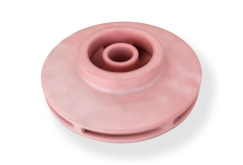
The aerospace industry thrives on innovation but is bound by the most rigorous standards of safety, performance, and reliability. In this high-stakes environment, 3D printed aerospace prototype models have become indispensable. They drastically compress development cycles, enable rapid iteration, and provide critical validation data.
Key takeaways
- Traditional aerospace prototyping, often reliant on CNC machining or custom tooling, is prohibitively expensive and slow for complex parts.
- The first critical decision is selecting the 3D printing process. The choice hinges on the prototype’s primary objective: Form, Fit, or Function.
- Ad-hoc prototyping wastes resources. A phased, gated process ensures each stage delivers maximum learning.
- Developing a 3D printed aerospace prototype is a sophisticated engineering endeavor that blends cutting-edge manufacturing with disciplined systems engineering.
Why Are 3D Printed Prototypes Transformative?
Traditional aerospace prototyping, often reliant on CNC machining or custom tooling, is prohibitively expensive and slow for complex parts. A single prototype can take months and cost hundreds of thousands of dollars. 3D printing disrupts this by offering:
- Unprecedented Speed: Concepts move from CAD to a physical part in days, not months.
- Radical Design Freedom: Complex internal channels, lattice structures, and topology-optimized geometries are possible, enabling performance gains impossible with machining.
- Cost-Effective Iteration: Engineers can test multiple design variants for the cost of one traditionally machined part, fostering true innovation.
- Part Consolidation: Assemblies of dozens of parts can be redesigned as a single, integrated component, reducing weight, assembly time, and potential failure points.
How Do You Choose the Right Manufacturing Technology?
The first critical decision is selecting the 3D printing process. The choice hinges on the prototype’s primary objective: Form, Fit, or Function.
| Technology | Best For | Key Aerospace Materials | Strengths | Limitations |
|---|---|---|---|---|
| Fused Deposition Modeling (FDM) | Large-scale form/fit models, ducting, non-structural housings. | ULTEM™ (PEI), PEEK, PEKK, high-temp Nylon. | Low-cost large parts, excellent chemical/thermal resistance with engineering materials. | Anisotropic strength, visible layer lines, lower dimensional accuracy. |
| Stereolithography (SLA) | High-detail visual models, aerodynamic surface studies, master patterns for tooling. | High-temp, castable, or durable resins. | Exceptional surface finish and feature resolution. | Brittle material properties, UV degradation, small build volumes. |
| Selective Laser Sintering (SLS) | Functional, ductile prototypes, housings, ductwork, jigs & fixtures. | Nylon PA12, PA11 (glass or carbon filled). | Isotropic strength, no support structures, good chemical resistance. | Powdery surface finish, moderate feature detail. |
| Multi Jet Fusion (MJF) | High-volume functional prototypes, complex end-use parts. | Nylon PA12, PA11. | Faster than SLS, excellent batch production, consistent mechanical properties. | Limited material palette, similar finish to SLS. |
| Direct Metal Laser Sintering (DMLS) | High-strength, high-temperature functional prototypes, structural brackets, engine components. | Ti-6Al-4V, Inconel 718, AlSi10Mg, Cobalt Chrome. | Flight-certifiable materials, extreme strength-to-weight ratios. | Very high cost, extensive post-processing (HIP, heat treat), support removal is difficult. |
Case in Point: UAV Development
A team designing a new unmanned aerial vehicle (UAV) used a multi-technology approach:
- Form/Fit: The fuselage shell was printed in large-format FDM using ULTEM to validate assembly and component placement.
- Aerodynamics: Wing surfaces were printed in SLA for wind tunnel testing, leveraging its smooth finish for accurate airflow data.
- Function: Internal structural brackets and landing gear were printed via DMLS in Ti-6Al-4V for load testing, simulating final material performance.
What Are the Non-Negotiable Aerospace Requirements?
Aerospace prototypes are not just models; they are test articles. Their value depends on how well they simulate the final part’s behavior under operational conditions.
How Do You Select and Qualify Materials?
Material selection is paramount. The chosen 3D printing material must be justified against the operational environment.
- Thermal Performance: Will the part be in the engine bay (150°C+) or the airframe (-55°C to 80°C)? PEEK/ULTEM for high temps, Nylon for ambient.
- Mechanical Loads: Is the part load-bearing or structural? DMLS metals or continuous fiber-reinforced composites are necessary.
- Environmental Exposure: Will it face fuel, hydraulic fluid, or UV radiation? Material data sheets must certify chemical compatibility.
- Outgassing & Flammability: For space applications, materials must meet NASA or ESA outgassing (ASTM E595) and flammability (FAR 25.853) standards.
Critical Step: Material Testing. Never assume a 3D printed material matches its raw stock properties. Print and test coupon samples (tensile, flexural, impact) in the intended print orientation to establish a statistically valid design allowables database for your specific printer and process parameters.
How Do You Integrate with Systems and Certification?
A prototype must prove its integration into the larger system.
- Avionics & EMI: Prototypes for avionics enclosures may need EMI/RFI shielding. This can be achieved with conductive coatings or using carbon-fiber filled materials that offer some inherent shielding.
- Aerodynamic & Fluidic Testing: Prototypes for wind tunnel or fluid flow testing must have a surface finish and dimensional accuracy suitable for the test. SLA or highly polished DMLS are often required.
- Path to Certification: Even for prototypes, adopting a certification-minded approach is wise. This means documenting the entire process: material lot, machine parameters, post-processing steps, and test results. This data is invaluable if the prototype evolves into a certified part.
What Does a Structured Development Process Look Like?
Ad-hoc prototyping wastes resources. A phased, gated process ensures each stage delivers maximum learning.
What is the Conceptual Design & Simulation Phase?
This is the most cost-effective phase to make changes.
- Define Requirements: Create a formal prototype requirements document. What question must this prototype answer? (e.g., “Does the bracket survive 2x limit load?” “What is the drag coefficient of this intake?”)
- Generative Design & Topology Optimization: Use software (like nTopology, Ansys) to create mass-optimized, organic shapes that meet load cases. These designs are often only manufacturable via 3D printing.
- High-Fidelity Simulation: Run Finite Element Analysis (FEA) for stress and Computational Fluid Dynamics (CFD) for airflow. Critically, use anisotropic material properties for processes like FDM. Simulate not just the load, but also the build process to predict warping and residual stress.
How Do You Execute the Build & Validation Phase?
This is where digital meets physical.
- Design for Additive Manufacturing (DfAM): Optimize the CAD model for the chosen process. This includes: Orientating for optimal strength and minimal supports. Hollowing with internal lattices to save weight and material. Adding necessary tolerances and clearances for mating parts.
- Managed Build: Partner with a specialized aerospace additive manufacturer. They provide controlled, repeatable processes, material traceability, and essential post-processing like Hot Isostatic Pressing (HIP) for metals or thermal annealing for plastics to relieve stress.
- Rigorous Testing: The prototype must answer the requirement. Testing may include: Dimensional Inspection (CMM scanning). Static and Fatigue Load Testing. Thermal Cycle Testing. Functional Testing in a rig or subsystem.
Real-World Example: Rocket Engine Injector
A propulsion company needed to test a new injector design with complex internal channels. Using DMLS with Inconel 718, they printed a functional prototype in three weeks. They subjected it to hot-fire testing, collecting data on combustion efficiency and thermal performance. The rapid iteration allowed by 3D printing led to an optimized design validated at a fraction of the traditional cost and time.
How to write a spec that gets priced correctly
A drawing is a contract. If it leaves a number open, the shop fills that number in with its own default. The default is rarely the one you had in mind. Put these five lines on every RFQ and most of the back-and-forth disappears before it starts.
- File format and units, with the model exported in millimetres
- Process and material grade, not a trade name
- Critical features and the tolerance each one needs
- Surface finish and the faces it applies to
- Quantity for the pilot build and for the year
The point is not paperwork. Each line removes a decision the shop would otherwise make for you. A complete RFQ comes back priced. An incomplete one comes back guessed.
What actually drives the price
Buyers usually push on material because it is the line they can see. In practice the material is rarely the biggest number on a quote. These five lines decide most of it:
- build volume and orientation
- layer height and support structure
- material grade and colour
- post-processing and hand finishing
- quantity per build plate
Ask for the quote split by line. A supplier who cannot break it down is guessing, and you will pay for the guess. The line you can usually renegotiate is the tolerance band, not the raw material.
Problems you will meet, and the fix
Every process has a failure mode it prefers. The same four show up again and again on this kind of work, and none of them are mysteries once you know what to look for.
- Warping on long flat faces where the part lifts off the plate
- Layer lines showing through a cosmetic surface
- Support scars on a mating face nobody flagged
- Dimensional drift on thin walls after cooling
Catch the fault on the first part, not the hundredth. A first-article check costs an hour. A bad batch costs the whole order. Write the check into the purchase order so nobody has to remember it.
What to check on the first article
The first article is the cheapest inspection you will ever buy. Use it properly and the rest of the run becomes boring, which is exactly what you want.
- Every dimension on the drawing, with the measured value written beside it.
- The material certificate, matched to the heat or lot number on the parts.
- The finish against the sample you approved, under the same light.
- Fit against the mating part, assembled rather than measured.
- Packaging, because parts that arrive damaged were never in tolerance.
Check in this order: datums, then mating features, then cosmetic faces. If the datums are wrong, every number after them is noise. Keep the report on file. When a problem shows up in month six, that document is the only thing that tells you what changed.
How to compare two quotes fairly
Two numbers are not comparable unless the scope matches. Line them up before you decide, because a low number with three gaps is not a low number.
Same drawing, same material, same finish, same inspection. Anything else is a different job wearing the same part number. Then look at what each quote leaves out. Freight, packaging, certificates and tooling are the usual gaps.
Ask each supplier to state their assumptions in writing. The one who does is usually the one who has run the process before.
Scaling from one part to a batch
The first part teaches you the process. The hundredth teaches you the process cost.
Watch three things as volume grows: setup amortisation, tool wear, and how much hand work the finish still needs. If the unit price barely moves between ten and a hundred, the cost sits in material or in hand work, not in setup. Ask which, because only one of them is negotiable.
Lead time behaves the same way. A one-off is scheduled around other jobs. A repeat order is scheduled around your forecast. Give the shop a forecast and the lead time gets shorter, not longer.
How to read a supplier's quote
A quote is a short document with a long shadow. Four things in it decide whether the job runs smoothly, and only one of them is the price.
- The scope line. It should name the process, the material and the finish, not just the part.
- The tolerance basis. General tolerance or the drawing, and which standard it follows.
- The exclusions. Tooling, freight, certificates and inspection are the usual omissions.
- The validity date. Material prices move, and an open-ended quote is a promise nobody can keep.
Read the exclusions before you read the total. A quote that leaves out tooling is not cheaper. It is a quote for a different job.
What to send with the first order
The first order sets the pattern for every order after it. Send a complete package once and the shop files it, and the second order takes a fraction of the time.
- A STEP or native model plus a PDF drawing carrying the same revision letter.
- The material callout by standard number, not by trade name.
- The finish and the exact faces it applies to.
- Any test the part must pass: fit, seal, drop, salt spray, dielectric.
- A contact who can answer a question inside one working day.
Then write down what was agreed. An email that confirms the material, the finish and the date is worth more than a longer purchase order that leaves them open.
When this is the wrong choice
A good supplier tells you when the process does not fit. These are the cases where we say so.
- The volume is so low that setup costs more than the parts are worth.
- The tolerance is tighter than the process can hold without a second operation.
- The geometry cannot be made without a tool feature that will not pay back.
- The material you need is not available in the form the process requires.
- The schedule is shorter than the tooling or setup time, and nobody has said so yet.
None of these are refusals. They are reasons to look at a different route, and the earlier that conversation happens the cheaper it is. The most expensive mistake in manufacturing is a process chosen before the question was understood.
What Are Common Pitfalls and How to Avoid Them?
- Ignoring Anisotropy: Assuming an FDM part is as strong vertically as horizontally is a common failure. Design and test with orientation in mind.
- Overlooking Post-Processing: A DMLS part straight from the machine is not ready for testing. Budget for and plan support removal, stress relief, HIP, and surface machining of critical features.
- Underestimating Cost of Quality: The cheapest quote may not include material certification, process documentation, or rigorous inspection. For aerospace, these are not optional.
- Skipping the “Why”: Printing a part “because we can” is wasteful. Every prototype must have a clear, stated objective tied to a key project risk or decision.
Developing a 3D printed aerospace prototype is a sophisticated engineering endeavor that blends cutting-edge manufacturing with disciplined systems engineering. Success is not measured by the speed of the print, but by the quality and actionability of the data the prototype generates. By strategically selecting the right technology for the right purpose, rigorously applying aerospace-grade material and process controls, and following a structured, simulation-driven development cycle, engineering teams can leverage additive manufacturing to its fullest potential. This approach transforms 3D printing from a rapid prototyping tool into a core competency for accelerating innovation, de-risking development, and paving a clearer path to flight certification in the modern aerospace industry.
How we can help
YiguProto runs 3D printing in house, from a single prototype to a production batch. We quote the process, the material and the finish as separate lines, so you can see where the money goes instead of arguing with one number.
Send a STEP file or a drawing and you get a DFM report in one to two business days. It flags the features that add cost and the features that will not hold tolerance on the process you picked.
Every order ships with an inspection report on the features you call out. If a part misses, we make it again. Ready to price a part? Start with a free quote and DFM review, or read more about our 3D printing. You can also talk to an engineer before you commit to a drawing.
Frequently asked questions
What material should I specify?
Specify by standard, not by trade name. A trade name can change under you between two orders; a standard number cannot. Then add the one property that actually decides the part, whether that is strength, heat resistance or chemical exposure.
What happens if a part is out of specification?
We measure it against the same drawing you approved and, if it misses, we make it again. What matters is that the report exists, because a disagreement without data is just an opinion.
How long does a first article take?
Usually a few business days once the drawing is frozen, and longer if tooling is involved. The date we give you is the date we confirm in writing, not the date we hope for.
Does the process work for prototypes as well as production?
Yes, and that is usually the point. Running the prototype on the production process removes a whole class of surprises, because the part you test is made the same way as the part you sell.
What files do you need in order to quote?
A STEP file plus a PDF drawing that carries the same revision letter. The model carries the geometry and the drawing carries the intent. When the two disagree, the shop picks one, and it is never the one you meant.
Is there a minimum order quantity?
No hard minimum. One part is fine. What changes with volume is which costs dominate, so a single unit is priced mostly on setup and a thousand units are priced mostly on cycle time and material.
The short version
Good parts reward the buyer who reads the data sheet and the drawing together. Pick the option for the property that matters, not for the price per kilo.
Tighten only what mates. Test a sample before the run. Then let the process do the rest.