
3D Printing
Are 3D Printed Interbody Fusion Devices the Future of Spinal Surgery?
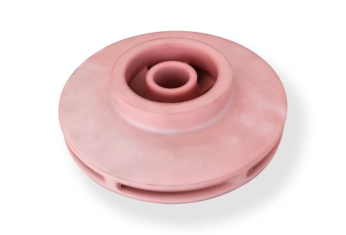
If you or a loved one is facing spinal fusion surgery, you’ve likely heard about traditional cages or spacers. But what if the implant could be designed specifically for your unique anatomy? What if it could actively encourage your own bone to grow through it, leading to a stronger, faster recovery? This isn’t science fiction—it’s the reality offered by 3D printed interbody fusion devices.
How Do 3D Printed Fusion Cages Actually Work?
At its core, spinal fusion aims to stabilize painful vertebral segments. The “interbody device” is the spacer placed between vertebrae to maintain height and foster bone growth. Traditional devices are typically machined from solid titanium or molded PEEK plastic, coming in a limited set of sizes and shapes.
3D printing, or additive manufacturing, flips this process. It builds the device layer by layer from a digital file, which is a game-changer. This allows for two fundamental innovations that directly address the limitations of off-the-shelf implants: patient-specific customization and engineered internal architecture.
Let’s look at how they stack up:
| Feature | 3D Printed Devices | Traditional (Machined/Molded) Devices |
|---|---|---|
| Fit & Personalization | Can be custom-designed from patient CT/MRI scans for an anatomical match. | Standardized sizes and shapes; may require intraoperative compromise or impaction. |
| Internal Structure | Precisely controlled porous lattice (e.g., 500-800µm pores) designed for bone ingrowth. | Mostly solid or with simple grooves; bone growth occurs around, not through, the device. |
| Material Versatility | Compatible with titanium alloys, PEEK, and even bioresorbable polymers. | Typically limited to one material per product line. |
| Primary Mechanism | Acts as a biomimetic scaffold that integrates with bone. | Acts as a mechanical spacer that holds bone graft. |
Why Is the Porous Design Such a Big Deal for Healing?
The scaffold-like porous structure is the superstar of 3D printed implants. Think of it not as a wall, but as a welcoming framework for your body’s natural healing process.
- Vascularization: The interconnected pores allow blood vessels to grow deep into the implant, delivering essential nutrients and oxygen.
- Osteoconduction: This vascular network enables bone-forming cells (osteoblasts) to migrate, attach, and proliferate throughout the device, not just at its edges.
- Stability: This biological fixation—bone growing into the implant—creates a incredibly stable construct. It significantly reduces the risk of implant subsidence (sinking into bone) or micromotion, which are common causes of pain and failure with traditional devices.
In short, it transforms the implant from a foreign object into an integrated part of your spine’s anatomy.
Where Are 3D Printed Spinal Implants Making the Most Impact?
The application of these devices is revolutionizing outcomes across the entire spine. Their benefits are most pronounced in complex cases where a perfect anatomical fit is critical.
Cervical Spine (Neck)
- Common Conditions: Degenerative disc disease, herniated discs, cervical stenosis.
- Why 3D Printing Helps: The delicate anatomy of the neck requires precision. A custom-fit cage minimizes the risk of irritating nearby nerves or the esophagus. Studies show fusion rates exceeding 92% within 6 months and significant reductions in post-operative dysphagia (trouble swallowing).
Lumbar Spine (Lower Back)
- Common Conditions: Spinal stenosis, spondylolisthesis (slipped vertebra), severe DDD.
- Why 3D Printing Helps: The lumbar spine bears the body’s weight. A device with optimal porosity and footprint distributes load evenly, preventing subsidence into the softer vertebral bone. This translates to higher patient satisfaction scores (~94%) and a faster return to daily activities.
Complex & Revision Surgeries
- Common Scenarios: Severe scoliosis correction, spinal trauma, or cases where previous fusion has failed (pseudarthrosis).
- Why 3D Printing Helps: Here, standard implants often fall short. Surgeons can design a device that fills a specific defect, fits unusual anatomy, or even incorporates screw pathways for integrated fixation—solutions simply impossible with traditional inventory.
A Real-World Case:
A 58-year-old with grade II lumbar spondylolisthesis experienced chronic leg pain and weakness. A 3D printed titanium implant, designed to match his lordotic curve and vertebral endplate morphology, was used. At the 3-month follow-up, early bone ingrowth was visible on CT scan within the implant’s pores. The patient reported a 70% reduction in pain and had successfully returned to his desk job, citing far less discomfort when sitting for extended periods.
What’s Driving the Rapid Growth of This Market?
The global market for 3D printed spinal devices is on a steep climb, with a projected CAGR of over 15% from 2023 to 2030 (Grand View Research). This isn’t just a trend; it’s a shift in standard of care.
- Demographic Drivers: Aging populations worldwide are leading to a higher incidence of degenerative spinal conditions.
- Clinical Demand: Surgeons and patients are increasingly seeking minimally invasive surgical (MIS) techniques, which require implants that can be inserted through smaller incisions but still achieve robust fusion. 3D printed devices are ideal for this.
- Material Innovation: The palette is expanding beyond titanium and PEEK to include bioresorbable materials like polyetheretherketone (PEEK) composites and calcium phosphate ceramics. These can provide temporary support and then slowly dissolve as the patient’s own bone takes over.
- Competitive Landscape: While giants like Medtronic, Stryker, and Zimmer Biomet lead in global reach, regional specialists are rising fast. In Asia, for instance, companies like our shop are gaining recognition for their rapid prototyping capabilities and deep collaboration with surgeons to push the boundaries of personalized design.
How to write a spec that gets priced correctly
A drawing is a contract. If it leaves a number open, the shop fills that number in with its own default. The default is rarely the one you had in mind. Put these five lines on every RFQ and most of the back-and-forth disappears before it starts.
- File format and units, with the model exported in millimetres
- Process and material grade, not a trade name
- Critical features and the tolerance each one needs
- Surface finish and the faces it applies to
- Quantity for the pilot build and for the year
The point is not paperwork. Each line removes a decision the shop would otherwise make for you. A complete RFQ comes back priced. An incomplete one comes back guessed.
What actually drives the price
Buyers usually push on material because it is the line they can see. In practice the material is rarely the biggest number on a quote. These five lines decide most of it:
- build volume and orientation
- layer height and support structure
- material grade and colour
- post-processing and hand finishing
- quantity per build plate
Ask for the quote split by line. A supplier who cannot break it down is guessing, and you will pay for the guess. The line you can usually renegotiate is the tolerance band, not the raw material.
Problems you will meet, and the fix
Every process has a failure mode it prefers. The same four show up again and again on this kind of work, and none of them are mysteries once you know what to look for.
- Warping on long flat faces where the part lifts off the plate
- Layer lines showing through a cosmetic surface
- Support scars on a mating face nobody flagged
- Dimensional drift on thin walls after cooling
Catch the fault on the first part, not the hundredth. A first-article check costs an hour. A bad batch costs the whole order. Write the check into the purchase order so nobody has to remember it.
What to check on the first article
The first article is the cheapest inspection you will ever buy. Use it properly and the rest of the run becomes boring, which is exactly what you want.
- Every dimension on the drawing, with the measured value written beside it.
- The material certificate, matched to the heat or lot number on the parts.
- The finish against the sample you approved, under the same light.
- Fit against the mating part, assembled rather than measured.
- Packaging, because parts that arrive damaged were never in tolerance.
Check in this order: datums, then mating features, then cosmetic faces. If the datums are wrong, every number after them is noise. Keep the report on file. When a problem shows up in month six, that document is the only thing that tells you what changed.
How to compare two quotes fairly
Two numbers are not comparable unless the scope matches. Line them up before you decide, because a low number with three gaps is not a low number.
Same drawing, same material, same finish, same inspection. Anything else is a different job wearing the same part number. Then look at what each quote leaves out. Freight, packaging, certificates and tooling are the usual gaps.
Ask each supplier to state their assumptions in writing. The one who does is usually the one who has run the process before.
Scaling from one part to a batch
The first part teaches you the process. The hundredth teaches you the process cost.
Watch three things as volume grows: setup amortisation, tool wear, and how much hand work the finish still needs. If the unit price barely moves between ten and a hundred, the cost sits in material or in hand work, not in setup. Ask which, because only one of them is negotiable.
Lead time behaves the same way. A one-off is scheduled around other jobs. A repeat order is scheduled around your forecast. Give the shop a forecast and the lead time gets shorter, not longer.
How to read a supplier's quote
A quote is a short document with a long shadow. Four things in it decide whether the job runs smoothly, and only one of them is the price.
- The scope line. It should name the process, the material and the finish, not just the part.
- The tolerance basis. General tolerance or the drawing, and which standard it follows.
- The exclusions. Tooling, freight, certificates and inspection are the usual omissions.
- The validity date. Material prices move, and an open-ended quote is a promise nobody can keep.
Read the exclusions before you read the total. A quote that leaves out tooling is not cheaper. It is a quote for a different job.
What to send with the first order
The first order sets the pattern for every order after it. Send a complete package once and the shop files it, and the second order takes a fraction of the time.
- A STEP or native model plus a PDF drawing carrying the same revision letter.
- The material callout by standard number, not by trade name.
- The finish and the exact faces it applies to.
- Any test the part must pass: fit, seal, drop, salt spray, dielectric.
- A contact who can answer a question inside one working day.
Then write down what was agreed. An email that confirms the material, the finish and the date is worth more than a longer purchase order that leaves them open.
When this is the wrong choice
A good supplier tells you when the process does not fit. These are the cases where we say so.
- The volume is so low that setup costs more than the parts are worth.
- The tolerance is tighter than the process can hold without a second operation.
- The geometry cannot be made without a tool feature that will not pay back.
- The material you need is not available in the form the process requires.
- The schedule is shorter than the tooling or setup time, and nobody has said so yet.
None of these are refusals. They are reasons to look at a different route, and the earlier that conversation happens the cheaper it is. The most expensive mistake in manufacturing is a process chosen before the question was understood.
Planning the ramp from prototype to production
The gap between one good part and a thousand identical ones is a plan, not a machine. Three decisions close it.
First, freeze the design. Every change after tooling starts is a re-cut, and re-cuts are where schedules go. Second, decide the inspection level. A prototype is checked by eye; a production part is checked against a report. Third, agree the change process in writing, including who pays for it.
Write the ramp down as dates and owners, not as intentions. A ramp plan with three names and three dates is worth more than a page of good intentions.
What documentation to expect
Paperwork is not bureaucracy when a part fails at the customer. It is the only record of what was agreed. A normal shipment should carry four documents.
- A dimensional report covering every callout on the drawing.
- A material certificate traceable to the heat or lot number.
- A finish or coating certificate where the specification requires one.
- A packing list that matches the carton labels.
If a supplier cannot produce these on request, they are not running a controlled process. Ask for one sample set before you place the first order and you will know exactly what you are buying.
How to handle a change after the order
Changes happen. What matters is whether the change is priced, scheduled and recorded, or absorbed quietly and discovered later.
Send the change as a new revision, not as a note in an email. Ask for three answers in writing: what it costs, what it does to the date, and what happens to material or tooling already committed. Then decide.
A change without a revision number is a rumour. The shop will build what it has on file, and both sides will be right and unhappy at the same time.
How the work actually runs, step by step
Most buyers see two numbers: a price and a date. Between them sits a sequence that decides both. On additive manufacturing work it looks like this.
- File review. The model and the drawing are checked against each other. Where they disagree, the shop stops and asks, because guessing is how scrap gets made.
- DFM feedback. The features that add cost and the features that will not hold tolerance are listed. This is the cheapest hour in the whole project.
- Setup or tooling. Fixtures, programs or a tool are built. Everything downstream inherits the quality of this step.
- First article. One part is made and measured against the drawing before anything else runs. Nothing is signed until it passes.
- Production. The run goes ahead with the parameters that produced the approved first article, not with new ones.
- Inspection and packing. The callouts are measured, the certificate is matched, and the parts are packed so they arrive in the condition they left in.
Ask any supplier to walk you through these six steps on your part. The answers tell you more about the shop than the price does.
Our solution for 3D Printed Interbody Fusion Devices
YiguProto runs 3D printing in house, from a single prototype to a production batch. We quote the process, the material and the finish as separate lines, so you can see where the money goes instead of arguing with one number.
Send a STEP file or a drawing and you get a DFM report in one to two business days. It flags the features that add cost and the features that will not hold tolerance on the process you picked.
Every order ships with an inspection report on the features you call out. If a part misses, we make it again. Ready to price a part? Start with a free quote and DFM review, or read more about our 3D printing. You can also talk to an engineer before you commit to a drawing.
FAQ about 3D Printed Interbody Fusion Devices
Does the process work for prototypes as well as production?
Yes, and that is usually the point. Running the prototype on the production process removes a whole class of surprises, because the part you test is made the same way as the part you sell.
Can 3D Printed Interbody Fusion Devices be made in small quantities?
Yes, and small quantities are where a good supplier earns the next order. Setup dominates the price at low volume, so the cheapest route is usually the one with the fewest operations, not the cheapest material.
How long does a first article take?
Usually a few business days once the drawing is frozen, and longer if tooling is involved. The date we give you is the date we confirm in writing, not the date we hope for.
How do I compare two quotes fairly?
Match the scope first: same drawing, same material, same finish, same inspection. Then read the exclusions. Freight, tooling and certificates are the usual gaps, and a low number with three gaps is not a low number.
What should I check before approving the parts?
Datums first, then the features that mate, then the cosmetic faces. Ask for a dimensional report, a material certificate and a finish sample. A part can be inside every tolerance and still not fit, so assemble one before you sign.
What tolerance can you hold on 3D Printed Interbody Fusion Devices?
The working default is ±0.1 mm on small features, ±0.3% on long spans. Tighter than that the process changes and so does the price, because every step tighter adds inspection time. Call out only the faces that mate with something else and leave the rest on the general tolerance.
The short version
3D Printed Interbody Fusion Devices rewards the buyer who reads the data sheet and the drawing together. Pick the option for the property that matters, not for the price per kilo.
Tighten only what mates. Test a sample before the run. Then let the process do the rest.