
3D Printing
How Do You Make 3D Printed Parts Stronger?
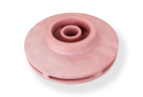
You’ve printed a part, but it broke. This is a common issue in 3D printing. The path from a digital file to a strong, functional component is not direct. True strength comes from a holistic approach that merges smart design, precise printing, and targeted post-processing. This guide moves beyond just picking a tough material. It provides a complete engineering framework.
Key takeaways
- Understanding failure modes is the first step to preventing them. Weaknesses often stem from the layer-by-layer nature of additive manufacturing.
- Your CAD model is the blueprint for strength. Good design leverages geometry to distribute stress and work with the printing process.
- The machine parameters you choose directly control the material’s microstructure and integrity.
- Post-processing can alter the material at a molecular level or add composite reinforcement.
Why Do 3D Printed Parts Fail?
Understanding failure modes is the first step to preventing them. Weaknesses often stem from the layer-by-layer nature of additive manufacturing.
- Weak Layer Adhesion: The bond between print layers (the Z-axis) is often the weakest point. Forces can cause de-lamination, where layers peel apart.
- Stress Concentrations: Sharp internal corners and sudden changes in wall thickness act as stress risers. They focus force, leading to cracks.
- Infill and Shell Issues: A part with low infill density or thin perimeter shells may crumple under load, even if the outer shape looks solid.
- Material Limitations: As-printed polymers often have internal stresses and may not be fully dense, limiting their mechanical performance.
Addressing these requires a strategy that spans the entire workflow.
How to Design for Maximum Strength?
Your CAD model is the blueprint for strength. Good design leverages geometry to distribute stress and work with the printing process.
Can Fillet and Chamfer Designs Help?
Yes, significantly. Fillets (rounded interior corners) are one of the most effective strength upgrades.
- The Science: A sharp corner creates a theoretical stress concentration factor (Kt) of near infinity. Even a small radius drastically reduces this. A fillet radius of just 4 times the wall thickness can reduce stress by about 90%.
- Practical Rule: For functional parts, use a minimum fillet radius of 1-3mm. This spreads load smoothly from one surface to another, preventing crack initiation.
- Chamfers (angled corners) are also useful, especially for easing assembly or reducing material at edges, though they are slightly less effective at stress relief than fillets.
Should You Add Ribs and Gussets?
Absolutely. Ribs are thin reinforcing walls, and gussets are triangular braces added to joints. They add stiffness with minimal weight.
- Design Guidelines: Rib height should not exceed 3 times its thickness, or it may buckle. Keep rib thickness 50-60% of the adjacent wall to prevent sink marks. Space ribs at least 2 times the wall thickness apart. Use gussets at base connections (like where a vertical post meets a horizontal plate) to resist bending moments.
A drone manufacturer used this. Their camera mount, printed in Nylon (PA12), kept failing at the base. Adding three radial gussets increased its stiffness by over 300% without adding significant weight.
What About Wall Thickness and Uniformity?
Consistency is key. Avoid sudden changes in wall thickness. A thick section next to a thin one cools at different rates, creating internal stresses and weak points.
- General Rule: Maintain uniform wall thickness where possible. For most load-bearing parts in FDM, a minimum wall thickness of 2-3mm is a good start.
- Hollowing vs. Solid: A part with thick, solid walls will be heavy and may warp. A smarter design uses consistent thin walls with strategic internal ribbing. This provides better strength-to-weight ratio.
How Do Print Settings Affect Strength?
The machine parameters you choose directly control the material’s microstructure and integrity.
What is the Best Infill Pattern and Density?
Infill provides internal support. The pattern and percentage are critical levers.
| Infill Pattern | Best Use Case | Strength Efficiency | Print Speed |
|---|---|---|---|
| Grid / Rectilinear | General purpose, good strength in X & Y. | High | Fast |
| Triangular / Tri-Hexagon | Isotropic strength; resists multi-directional force. | Very High | Medium |
| Gyroid | Excellent for flexible parts or fluid dynamics; good strength in all directions. | High | Slow |
| Concentric | Good for parts with radial or hoop stress. | Medium (direction-dependent) | Medium |
- Density Guidelines: For visual models, 10-20% is fine. For functional parts, 40-60% offers a great balance. For high-stress areas, go to 80-100%, but consider that solid top/bottom layers (5-6 layers) are often more impactful than 100% infill.
- Advanced Tip: Use variable infill density in your slicer. Apply high density (80%) only at stress points like screw holes, and lower density (25%) elsewhere to save time and material.
How Critical is Print Orientation?
This is paramount. A part is always stronger along the layer lines (X-Y plane) than across them (Z-axis).
- The Rule: Orient your part so that the primary load is applied parallel to the build plate. For example, print a hook so the pulling force acts across the layers, not trying to peel them apart.
- Data Point: A standardized test hook printed in PLA showed a Z-axis tensile strength of 38 MPa, but an X-Y axis strength of 49 MPa—a difference of nearly 30%.
A robotics team learned this the hard way. Their PETG motor mount, printed upright, snapped at the layers. Laying it flat for the next print made it survive the force.
Does Layer Height Matter?
Smaller layer heights generally improve Z-axis strength and surface finish because they increase the bonding area between layers.
- Trade-off: A 0.15mm layer will have about 25% better layer adhesion than a 0.3mm layer with the same material, but it will take twice as long to print.
- Nozzle Size: Using a larger nozzle (0.6mm or 0.8mm) with a proportional layer height can also increase strength. The thicker, wider extruded lines bond with more material contact, though surface detail is lost.
Is Shell/Perimeter Count Important?
The outer perimeters (shells) form a continuous “skin” that takes most of the impact and bending stress.
- Best Practice: For functional parts, use 3-5 perimeter walls. This creates a robust outer structure before the infill pattern begins. More perimeters often contribute more to strength than simply increasing infill percentage.
Which Post-Processing Methods Add Real Strength?
Post-processing can alter the material at a molecular level or add composite reinforcement.
Can Annealing Truly Strengthen Parts?
Thermal annealing is a game-changer for many polymers. It involves heating the part to just below its glass transition temperature (Tg) in a controlled oven.
- What It Does: It allows polymer chains to relax and re-crystallize, relieving internal stresses and increasing crystallinity. This boosts heat resistance, stiffness, and often tensile strength.
- Process by Material: PLA: Heat to 60-70°C (140-158°F) for 30-60 minutes. Note: PLA can warp or shrink (~5%) without constraint. ABS/ASA: Heat to 100-110°C (212-230°F) for 30-45 minutes. Nylon (PA6/PA12): Heat to 120-150°C (248-302°F) for 1-2 hours. Often done in mineral oil to prevent oxidation.
- Result: Annealed PLA parts can see a 40% increase in heat deflection temperature (HDT) and a 15-25% increase in tensile strength.
How Does Epoxy Coating or Impregnation Work?
Epoxy resin can be applied as a surface coating or used to impregnate a part.
- Coating: Brushing or dipping in a low-viscosity epoxy creates a hard, waterproof shell. This greatly improves abrasion and chemical resistance and can seal porous prints.
- Vacuum Impregnation: This advanced process pulls a vacuum on the part, then submerges it in epoxy. The resin is forced into every microscopic pore and layer line, creating a dense, unified composite. This can dramatically improve strength and make the part air and water-tight.
What About Fiber Reinforcement?
This is the pinnacle of strengthening. It involves adding continuous fibers like carbon fiber or fiberglass during or after printing.
- In-process (Markforged): Specialized FDM printers use a second nozzle to lay continuous strands of fiber into a plastic matrix (like Onyx). This creates parts with strength rivaling aluminum.
- Post-process: Methods like fiber wrapping or applying pre-preg carbon patches with epoxy can reinforce high-stress areas of a standard 3D print.
Case Study: A Formula SAE team replaced a machined aluminum brake pedal with a 3D printed Nylon + continuous carbon fiber part. The new pedal was 60% lighter and withstood the same 2 kN load without failure, demonstrating true performance enhancement.
How to write a spec that gets priced correctly
A drawing is a contract. If it leaves a number open, the shop fills that number in with its own default. The default is rarely the one you had in mind. Put these five lines on every RFQ and most of the back-and-forth disappears before it starts.
- File format and units, with the model exported in millimetres
- Process and material grade, not a trade name
- Critical features and the tolerance each one needs
- Surface finish and the faces it applies to
- Quantity for the pilot build and for the year
The point is not paperwork. Each line removes a decision the shop would otherwise make for you. A complete RFQ comes back priced. An incomplete one comes back guessed.
What actually drives the price
Buyers usually push on material because it is the line they can see. In practice the material is rarely the biggest number on a quote. These five lines decide most of it:
- build volume and orientation
- layer height and support structure
- material grade and colour
- post-processing and hand finishing
- quantity per build plate
Ask for the quote split by line. A supplier who cannot break it down is guessing, and you will pay for the guess. The line you can usually renegotiate is the tolerance band, not the raw material.
Problems you will meet, and the fix
Every process has a failure mode it prefers. The same four show up again and again on this kind of work, and none of them are mysteries once you know what to look for.
- Warping on long flat faces where the part lifts off the plate
- Layer lines showing through a cosmetic surface
- Support scars on a mating face nobody flagged
- Dimensional drift on thin walls after cooling
Catch the fault on the first part, not the hundredth. A first-article check costs an hour. A bad batch costs the whole order. Write the check into the purchase order so nobody has to remember it.
What to check on the first article
The first article is the cheapest inspection you will ever buy. Use it properly and the rest of the run becomes boring, which is exactly what you want.
- Every dimension on the drawing, with the measured value written beside it.
- The material certificate, matched to the heat or lot number on the parts.
- The finish against the sample you approved, under the same light.
- Fit against the mating part, assembled rather than measured.
- Packaging, because parts that arrive damaged were never in tolerance.
Check in this order: datums, then mating features, then cosmetic faces. If the datums are wrong, every number after them is noise. Keep the report on file. When a problem shows up in month six, that document is the only thing that tells you what changed.
How to compare two quotes fairly
Two numbers are not comparable unless the scope matches. Line them up before you decide, because a low number with three gaps is not a low number.
Same drawing, same material, same finish, same inspection. Anything else is a different job wearing the same part number. Then look at what each quote leaves out. Freight, packaging, certificates and tooling are the usual gaps.
Ask each supplier to state their assumptions in writing. The one who does is usually the one who has run the process before.
Scaling from one part to a batch
The first part teaches you the process. The hundredth teaches you the process cost.
Watch three things as volume grows: setup amortisation, tool wear, and how much hand work the finish still needs. If the unit price barely moves between ten and a hundred, the cost sits in material or in hand work, not in setup. Ask which, because only one of them is negotiable.
Lead time behaves the same way. A one-off is scheduled around other jobs. A repeat order is scheduled around your forecast. Give the shop a forecast and the lead time gets shorter, not longer.
How to read a supplier's quote
A quote is a short document with a long shadow. Four things in it decide whether the job runs smoothly, and only one of them is the price.
- The scope line. It should name the process, the material and the finish, not just the part.
- The tolerance basis. General tolerance or the drawing, and which standard it follows.
- The exclusions. Tooling, freight, certificates and inspection are the usual omissions.
- The validity date. Material prices move, and an open-ended quote is a promise nobody can keep.
Read the exclusions before you read the total. A quote that leaves out tooling is not cheaper. It is a quote for a different job.
How to Create a Strength-Optimization Workflow?
Start with this step-by-step approach for your next critical part:
- Design Phase: Apply generous fillets (R2mm+) to all internal corners. Add ribs or gussets to any long, unsupported span or 90-degree joint. Aim for uniform wall thickness (~3mm).
- Slicing Phase: Orient the part so the main force is in the X-Y plane. Set 3-5 perimeter shells. Choose Triangular or Gyroid infill at 40-60% density. Use a moderate layer height (0.2mm) for a good strength/speed balance.
- Post-Processing Phase: For PLA, ABS, or Nylon parts in warm or stressed environments, anneal them. For parts exposed to weather or chemicals, apply an epoxy coating. For the ultimate strength-to-weight ratio, explore continuous fiber reinforcement.
Creating strong 3D printed parts is a deliberate engineering process, not a happy accident. Strength is built through the synergy of smart design, precise process control, and strategic post-processing. By understanding and applying the principles of stress distribution through fillets and ribs, optimizing the anisotropic nature of prints through orientation, and enhancing material properties with annealing or composites, you can reliably produce parts that meet and exceed functional demands. Stop treating 3D printing as just a prototyping tool. With this holistic approach, it becomes a viable method for creating robust, end-use components that perform.
Our solution for Make 3D Printed Parts Stronger
YiguProto runs 3D printing in house, from a single prototype to a production batch. We quote the process, the material and the finish as separate lines, so you can see where the money goes instead of arguing with one number.
Send a STEP file or a drawing and you get a DFM report in one to two business days. It flags the features that add cost and the features that will not hold tolerance on the process you picked.
Every order ships with an inspection report on the features you call out. If a part misses, we make it again. Ready to price a part? Start with a free quote and DFM review, or read more about our 3D printing. You can also talk to an engineer before you commit to a drawing.
FAQ about Make 3D Printed Parts Stronger
How long does a first article take?
Usually a few business days once the drawing is frozen, and longer if tooling is involved. The date we give you is the date we confirm in writing, not the date we hope for.
What material should I specify?
Specify by standard, not by trade name. A trade name can change under you between two orders; a standard number cannot. Then add the one property that actually decides the part, whether that is strength, heat resistance or chemical exposure.
Can Make 3D Printed Parts Stronger be made in small quantities?
Yes, and small quantities are where a good supplier earns the next order. Setup dominates the price at low volume, so the cheapest route is usually the one with the fewest operations, not the cheapest material.
Does the process work for prototypes as well as production?
Yes, and that is usually the point. Running the prototype on the production process removes a whole class of surprises, because the part you test is made the same way as the part you sell.
What tolerance can you hold on Make 3D Printed Parts Stronger?
The working default is ±0.1 mm on small features, ±0.3% on long spans. Tighter than that the process changes and so does the price, because every step tighter adds inspection time. Call out only the faces that mate with something else and leave the rest on the general tolerance.
What is Make 3D Printed Parts Stronger used for?
Make 3D Printed Parts Stronger turns up wherever the part has to do a real job at a predictable cost: brackets, housings, fixtures, covers and the fittings that hold them together. The honest test is whether the properties match the load and the environment, not whether the material is fashionable.
The short version
Make 3D Printed Parts Stronger rewards the buyer who reads the data sheet and the drawing together. Pick the option for the property that matters, not for the price per kilo.
Tighten only what mates. Test a sample before the run. Then let the process do the rest.