
3D Printing
How Do You 3D Print a Functional Prototype for a Light Guide?
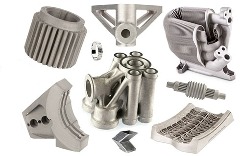
If you’re developing a next-generation LED fixture, a medical endoscope, or a sleek display, you know the light guide column is at its heart—the component that silently and precisely controls every photon. Traditionally, prototyping this optical core meant weeks of waiting and thousands invested in injection molds, only to hope the design was right.
Key takeaways
- A light guide column works on principles of total internal reflection (TIR) and controlled scattering to transport light from a source (like an LED) to a specific output area with desired uniformity.
- Success begins at the CAD stage. This phase is about translating optical theory into a printable geometry.
- Your material choice directly dictates the optical fidelity and mechanical performance of the prototype.
- A perfect design can be ruined by poor execution. Precision in printing and finishing is non-negotiable for optical parts.
What Makes a 3D-Printed Prototype Essential for Light Guide Development?
A light guide column works on principles of total internal reflection (TIR) and controlled scattering to transport light from a source (like an LED) to a specific output area with desired uniformity. A 3D-printed prototype of this component is a functional testbed that allows you to validate three critical factors before committing to mass production tooling:
- Light Conduction Efficiency: How much of the input light successfully travels through the guide.
- Output Uniformity: Whether the emitted light is evenly distributed without hot spots or dark zones.
- Mechanical & Optical Integration: How the part fits within the assembly and interfaces with other components.
The unique value of additive manufacturing here is its ability to create complex internal and surface features—such as micro-prisms, light-extraction textures, or free-form parabolic shapes—that are either impossible or prohibitively expensive to produce with conventional injection molding at the prototype stage. For instance, a lighting company reported cutting their initial prototype lead time from 4 weeks to 3 days and cost from $2,000 to $150 by switching from traditional molding to 3D printing, enabling multiple design iterations within the original timeframe.
How Do You Design a Model for Optimal Light Performance?
Success begins at the CAD stage. This phase is about translating optical theory into a printable geometry.
Which Software and Design Principles Are Critical?
Professional computer-aided design (CAD) software like SolidWorks, CATIA, or UG is essential for creating the precise, watertight models required. Beyond basic shape, your design must incorporate optical fundamentals:
- Inlet Surface Optimization: The light entry point must be extremely smooth. A surface roughness (Ra) between 0.4 – 0.8 μm is a common target to minimize initial reflection losses and maximize light intake.
- Internal Light Path Control: To steer light and prevent losses, incorporate features like small prisms (0.5-1 mm tall) or reflective grooves along the column’s length. The angles of these features are tuned to ensure TIR.
- Outlet Engineering: The output surface might be smooth for direct illumination or intentionally textured with microstructures to diffuse light evenly. These textures can be simulated and then directly printed.
A real-world example underscores this: a medical device firm’s first prototype had only 65% light conduction efficiency. The culprit was a suboptimal inlet surface. By redesigning it to achieve an Ra of 0.6 μm, they boosted efficiency to 88%.
What Materials and Techniques Yield the Best Optical Results?
Your material choice directly dictates the optical fidelity and mechanical performance of the prototype. The table below compares the most common options for light guide prototyping.
| Material | Light Transmission (Typical) | Key Advantage | Primary Limitation | Ideal Application |
|---|---|---|---|---|
| Clear Photopolymer Resin | 90-95% | Excellent for surface finish and fine detail (resolution ±0.02mm). | Can be brittle; may require extensive post-curing. | High-precision optics for medical devices (endoscopes), sensors. |
| Translucent PLA | 80-85% | Low cost, easy to print, good for early form/fit tests. | Lower optical clarity and heat resistance. | Initial conceptual prototypes, non-critical light guides. |
| Transparent PETG | 85-90% | Good durability and impact resistance with better clarity than PLA. | More prone to stringing during printing. | Durable prototypes for outdoor lighting or automotive fixtures. |
Expert Insight on Resin Selection: For applications demanding laboratory-grade optical performance, research from the Federal Institute for Materials Research and Testing (BAM) in Germany provides a critical checklist:
- High Transmission (>85%) in the relevant wavelength (e.g., visible to near-infrared).
- Low Autofluorescence to avoid signal contamination in sensing applications.
- Refractive Index (RI >1.5) to match common optical polymers like PMMA or polycarbonate.
- Surface Quality achievable through post-processing, with surface roughness (Rq) reaching as low as 0.07 μm, rivaling polished glass.
Beyond Desktop Printing: For prototypes involving micro-optics or direct integration with optical fibers, Two-Photon Polymerization (2PP or TPP) is a revolutionary high-resolution technique. It enables direct printing of free-form optical splitters, photonic wire bonds, and nano-gratings with features smaller than a micron, opening doors to applications in telecom, biosensing, and quantum technologies.
What Are the Critical Steps for Printing and Post-Processing?
A perfect design can be ruined by poor execution. Precision in printing and finishing is non-negotiable for optical parts.
How Do You Ensure a Flawless Print?
The printing phase requires vigilant monitoring to avoid defects that scatter or block light:
- Calibration: Ensure perfect build plate leveling and Z-offset. The first layer must be flawless.
- Parameter Tuning: Use material-specific settings. For resins, ensure correct layer cure times; for filaments, use optimal temperatures and speeds to prevent bubbles or warping.
- Defect Prevention: Watch for layer misalignment (causes light-leaking “gaps”) and bubbles within the material (scatter light). Using degassed resin or thoroughly dried filament is crucial.
Why Is Post-Processing a Make-or-Break Phase?
For light guides, printing is only half the job. Post-processing transforms a rough print into an optical component:
- Support Removal: Remove supports carefully to avoid scratching critical optical surfaces.
- Sanding & Polishing: Progress through increasingly fine grits of sandpaper (e.g., 400 to 800 to 1500+ grit), followed by polishing compounds. This reduces surface roughness to minimize light scattering.
- Advanced Finishing (Optional): For maximum performance, apply an anti-reflective coating. A thin layer (0.5-1 μm) on the inlet and outlet surfaces can boost light transmission by 5-10%.
- Final Curing (for Resins): Ensure the part is fully post-cured under UV light to achieve final mechanical strength and stable optical properties.
How Do You Quantifiably Test the Prototype’s Performance?
Functional testing closes the loop, providing data to validate or improve the design. Three core tests are essential:
| Test | Method & Tool | Goal & Success Metric |
|---|---|---|
| Light Conduction Efficiency | Use a stable light source and a lux meter or integrating sphere. Measure luminous flux at inlet and outlet. | Efficiency = (Output Flux / Input Flux) x 100%. Target >80% for most applications; high-end prototypes aim for >90%. |
| Light Uniformity | Illuminate the guide and use a camera with a light meter app or a 2D colorimeter to capture the output surface. | A uniform, gradient-free light field without dark spots or bright rings. Quantify by standard deviation of pixel intensity. |
| Mechanical & Dimensional Fit | Use calipers, optical comparators, or CT scanning. Perform assembly test with adjacent parts. | The prototype fits seamlessly into the intended housing without force, ensuring proper alignment with light source and lenses. |
Iterate Based on Data: If efficiency is low, consider redesigning the light inlet angle or internal prism geometry. One client increased efficiency from 75% to 86% simply by adjusting prism angles from 45° to 50°. If uniformity is poor, the pattern or density of the output surface textures may need revision.
How to write a spec that gets priced correctly
A drawing is a contract. If it leaves a number open, the shop fills that number in with its own default. The default is rarely the one you had in mind. Put these five lines on every RFQ and most of the back-and-forth disappears before it starts.
- File format and units, with the model exported in millimetres
- Process and material grade, not a trade name
- Critical features and the tolerance each one needs
- Surface finish and the faces it applies to
- Quantity for the pilot build and for the year
The point is not paperwork. Each line removes a decision the shop would otherwise make for you. A complete RFQ comes back priced. An incomplete one comes back guessed.
What actually drives the price
Buyers usually push on material because it is the line they can see. In practice the material is rarely the biggest number on a quote. These five lines decide most of it:
- build volume and orientation
- layer height and support structure
- material grade and colour
- post-processing and hand finishing
- quantity per build plate
Ask for the quote split by line. A supplier who cannot break it down is guessing, and you will pay for the guess. The line you can usually renegotiate is the tolerance band, not the raw material.
Problems you will meet, and the fix
Every process has a failure mode it prefers. The same four show up again and again on this kind of work, and none of them are mysteries once you know what to look for.
- Warping on long flat faces where the part lifts off the plate
- Layer lines showing through a cosmetic surface
- Support scars on a mating face nobody flagged
- Dimensional drift on thin walls after cooling
Catch the fault on the first part, not the hundredth. A first-article check costs an hour. A bad batch costs the whole order. Write the check into the purchase order so nobody has to remember it.
What to check on the first article
The first article is the cheapest inspection you will ever buy. Use it properly and the rest of the run becomes boring, which is exactly what you want.
- Every dimension on the drawing, with the measured value written beside it.
- The material certificate, matched to the heat or lot number on the parts.
- The finish against the sample you approved, under the same light.
- Fit against the mating part, assembled rather than measured.
- Packaging, because parts that arrive damaged were never in tolerance.
Check in this order: datums, then mating features, then cosmetic faces. If the datums are wrong, every number after them is noise. Keep the report on file. When a problem shows up in month six, that document is the only thing that tells you what changed.
How to compare two quotes fairly
Two numbers are not comparable unless the scope matches. Line them up before you decide, because a low number with three gaps is not a low number.
Same drawing, same material, same finish, same inspection. Anything else is a different job wearing the same part number. Then look at what each quote leaves out. Freight, packaging, certificates and tooling are the usual gaps.
Ask each supplier to state their assumptions in writing. The one who does is usually the one who has run the process before.
Scaling from one part to a batch
The first part teaches you the process. The hundredth teaches you the process cost.
Watch three things as volume grows: setup amortisation, tool wear, and how much hand work the finish still needs. If the unit price barely moves between ten and a hundred, the cost sits in material or in hand work, not in setup. Ask which, because only one of them is negotiable.
Lead time behaves the same way. A one-off is scheduled around other jobs. A repeat order is scheduled around your forecast. Give the shop a forecast and the lead time gets shorter, not longer.
How to read a supplier's quote
A quote is a short document with a long shadow. Four things in it decide whether the job runs smoothly, and only one of them is the price.
- The scope line. It should name the process, the material and the finish, not just the part.
- The tolerance basis. General tolerance or the drawing, and which standard it follows.
- The exclusions. Tooling, freight, certificates and inspection are the usual omissions.
- The validity date. Material prices move, and an open-ended quote is a promise nobody can keep.
Read the exclusions before you read the total. A quote that leaves out tooling is not cheaper. It is a quote for a different job.
What to send with the first order
The first order sets the pattern for every order after it. Send a complete package once and the shop files it, and the second order takes a fraction of the time.
- A STEP or native model plus a PDF drawing carrying the same revision letter.
- The material callout by standard number, not by trade name.
- The finish and the exact faces it applies to.
- Any test the part must pass: fit, seal, drop, salt spray, dielectric.
- A contact who can answer a question inside one working day.
Then write down what was agreed. An email that confirms the material, the finish and the date is worth more than a longer purchase order that leaves them open.
What Are the Trade-Offs and Emerging Opportunities?
Understanding the landscape helps set realistic expectations and plan for the future.
What Are the Current Advantages and Limitations?
- Advantages: Unmatched speed (prototypes in days), radical design freedom for complex light paths, and significant cost savings by eliminating hard tooling for iterative testing.
- Challenges: The post-processing workload for polishing can be time-intensive. Material properties of printed plastics (like long-term yellowing or thermal stability) may not match final production-grade optics. Achieving batch-to-batch consistency in optical performance requires tightly controlled processes.
What Does the Future Hold?
The field is advancing rapidly, moving beyond simple prototyping:
- Direct Digital Manufacturing: Companies like Luximprint now offer platforms to 3D print functional, large-format light guiding plates with integrated micro-textures, bypassing traditional polishing and suitable for low-volume production.
- Integration with Photonics: The frontier lies in using high-resolution 3D printing (like 2PP) to create monolithic photonic devices—such as splitters and couplers printed directly onto fiber tips—for sensing, telecommunications, and quantum computing.
3D printing a light guide column prototype is a powerful, iterative process that merges optical design with advanced manufacturing. By mastering the workflow—from optical-CAD principles and strategic material selection to meticulous post-processing and data-driven testing—you transform a digital concept into a validated physical component. This approach de-risks product development, saves substantial time and cost, and provides the tangible proof needed to secure stakeholder buy-in for final production. As technologies like high-resolution resin printing and Two-Photon Polymerization mature, the line between prototype and end-use optical part continues to blur, offering unprecedented opportunities for innovation in lighting, medical technology, and beyond.
Our solution for 3D Print
YiguProto runs 3D printing in house, from a single prototype to a production batch. We quote the process, the material and the finish as separate lines, so you can see where the money goes instead of arguing with one number.
Send a STEP file or a drawing and you get a DFM report in one to two business days. It flags the features that add cost and the features that will not hold tolerance on the process you picked.
Every order ships with an inspection report on the features you call out. If a part misses, we make it again. Ready to price a part? Start with a free quote and DFM review, or read more about our 3D printing. You can also talk to an engineer before you commit to a drawing.
FAQ about 3D Print
What is the lead time for 3D Print?
Expect 2 to 5 business days for a first batch. Tooling, material stock and the finishing queue all move that number, so we confirm the date in writing before the run starts rather than after.
Is there a minimum order quantity?
No hard minimum. One part is fine. What changes with volume is which costs dominate, so a single unit is priced mostly on setup and a thousand units are priced mostly on cycle time and material.
What should I check before approving the parts?
Datums first, then the features that mate, then the cosmetic faces. Ask for a dimensional report, a material certificate and a finish sample. A part can be inside every tolerance and still not fit, so assemble one before you sign.
How do I compare two quotes fairly?
Match the scope first: same drawing, same material, same finish, same inspection. Then read the exclusions. Freight, tooling and certificates are the usual gaps, and a low number with three gaps is not a low number.
How long does a first article take?
Usually a few business days once the drawing is frozen, and longer if tooling is involved. The date we give you is the date we confirm in writing, not the date we hope for.
What is 3D Print used for?
3D Print turns up wherever the part has to do a real job at a predictable cost: brackets, housings, fixtures, covers and the fittings that hold them together. The honest test is whether the properties match the load and the environment, not whether the material is fashionable.
The short version
3D Print rewards the buyer who reads the data sheet and the drawing together. Pick the option for the property that matters, not for the price per kilo.
Tighten only what mates. Test a sample before the run. Then let the process do the rest.