
3D Printing
Is Ultra-High Precision 3D Printing the Future of Prototyping?
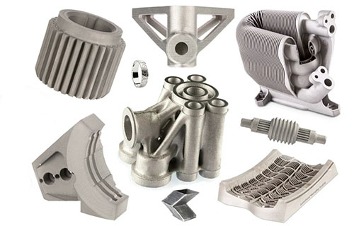
In the race to innovate, the prototype phase is often the most critical—and most frustrating—bottleneck. Engineers and product teams face a constant tug-of-war: the need for rapid iteration clashes with the demand for prototypes that are dimensionally, functionally, and materially representative of the final product.
Key takeaways
- In the context of professional prototyping, “ultra-high precision” refers to the ability to consistently produce parts with dimensional tolerances below ±0.025 mm (25 microns) and to reliably reproduce feature resolutions as fine as 0.01 mm (10 microns).
- The value of this precision is measured by the longstanding problems it eliminates in the product development cycle.
- The precision of the machine is only half the equation; the materials must match the ambition. The palette has evolved far beyond basic plastics.
- Adopting this technology requires a clear understanding of its operational and financial model.
What Defines “Ultra-High Precision” in 3D Printing?
In the context of professional prototyping, “ultra-high precision” refers to the ability to consistently produce parts with dimensional tolerances below ±0.025 mm (25 microns) and to reliably reproduce feature resolutions as fine as 0.01 mm (10 microns). This level of fidelity moves 3D printing from a tool for visual models into the realm of functional, test-ready prototypes that can be used for fit, form, and function testing.
This capability is primarily delivered by two advanced families of additive manufacturing technologies:
- Micro-Scale Vat Photopolymerization: This includes advanced iterations of SLA (Stereolithography) and, more notably, Projection Micro-Stereolithography (PµSL). PµSL uses a high-resolution digital light projector and precision optics to cure photopolymer resin with exceptional detail, achieving layer heights and feature sizes in the single-digit micron range. It’s the workhorse for micro-optics, microfluidics, and intricate medical devices.
- Metal Additive Manufacturing at the Micro-Scale: Technologies like Micro Laser Sintering (µLS) and two-photon polymerization (2PP) directly fabricate metal or polymer parts with micro-scale features. 2PP, for instance, uses a focused laser to cure resin at a tiny focal point, allowing it to “draw” features smaller than the wavelength of light itself.
What Problems Does This Precision Solve in Real-World Prototyping?
The value of this precision is measured by the longstanding problems it eliminates in the product development cycle.
How Does It Enable True “First-Part” Functional Testing?
Historically, a prototype might be “close enough” for visual review but would require tooling and traditional manufacturing to produce a part accurate enough for functional testing. Ultra-high precision 3D printing changes this.
- Case in Point: A Microfluidic Diagnostic Chip. A biotech company developing a “lab-on-a-chip” for blood analysis needed prototypes with channel widths of 50±5 microns to ensure precise fluid dynamics for biomarker detection. Using PµSL technology, they could print fully enclosed, leak-tight microfluidic channels in a single piece. This allowed them to test fluid flow, mixing, and reaction kinetics with their actual assay chemistry on the very first prototypes, shaving months off their R&D timeline compared to waiting for expensive and slow silicon or glass micro-machining.
How Does It Overcome “Design-for-Manufacturability” Compromises?
Engineers often have to simplify designs early on because they know certain features—like undercuts, internal lattices, or conformal cooling channels—are impossible or prohibitively expensive to prototype with traditional methods.
- Case in Point: Conformal Cooling in Injection Molds. A manufacturer of consumer electronics wanted to reduce cycle times for a plastic housing. The ideal solution was a mold insert with curved cooling channels that perfectly followed the contour of the part—a textbook case for conformal cooling. Using metal 3D printing (DMLS) with ultra-high precision, they directly printed a fully dense, hardened tool steel insert with these complex internal channels. The prototype mold insert was tested in an actual press, demonstrating a 30% reduction in cycle time and more uniform part cooling. This validated the design before committing to final, full-scale production tooling.
What Advanced Materials Are Making This Possible?
The precision of the machine is only half the equation; the materials must match the ambition. The palette has evolved far beyond basic plastics.
| Material Category | Example Materials | Key Properties for Prototyping | Ideal Application |
|---|---|---|---|
| Engineering & High-Temp Photopolymers | Ceramic-Filled Resins, High-Temp Resins (HDT >200°C), ABS-Like & PP-Like Resins | Thermal stability, stiffness, toughness, and smooth surface finish. Mimic production thermoplastics. | Functional housings, under-hood automotive components, snap-fit assemblies. |
| Biocompatible & Medical-Grade Materials | Class I & IIa Biocompatible Resins (ISO 10993), Dental SG Resins | Certified for skin contact or short-term mucosal contact. Sterilizable. | Surgical guides, custom implant prototypes, wearable medical device housings. |
| Advanced Metals | Stainless Steel 316L, Titanium Ti64, Cobalt-Chrome, Aluminum AlSi10Mg | Full density, mechanical properties matching wrought material, excellent thermal characteristics. | Aerospace brackets, functional engine components, patient-specific implant trials. |
| Specialty Composites & Ceramics | Silica-Filled Resins, Alumina Suspensions | Extreme hardness, high-temperature resistance, and specialized dielectric or thermal properties. | Micro-electronics packaging, RF antenna prototypes, high-wear jigs and fixtures. |
How to write a spec that gets priced correctly
A drawing is a contract. If it leaves a number open, the shop fills that number in with its own default. The default is rarely the one you had in mind. Put these five lines on every RFQ and most of the back-and-forth disappears before it starts.
- File format and units, with the model exported in millimetres
- Process and material grade, not a trade name
- Critical features and the tolerance each one needs
- Surface finish and the faces it applies to
- Quantity for the pilot build and for the year
The point is not paperwork. Each line removes a decision the shop would otherwise make for you. A complete RFQ comes back priced. An incomplete one comes back guessed.
What actually drives the price
Buyers usually push on material because it is the line they can see. In practice the material is rarely the biggest number on a quote. These five lines decide most of it:
- build volume and orientation
- layer height and support structure
- material grade and colour
- post-processing and hand finishing
- quantity per build plate
Ask for the quote split by line. A supplier who cannot break it down is guessing, and you will pay for the guess. The line you can usually renegotiate is the tolerance band, not the raw material.
Problems you will meet, and the fix
Every process has a failure mode it prefers. The same four show up again and again on this kind of work, and none of them are mysteries once you know what to look for.
- Warping on long flat faces where the part lifts off the plate
- Layer lines showing through a cosmetic surface
- Support scars on a mating face nobody flagged
- Dimensional drift on thin walls after cooling
Catch the fault on the first part, not the hundredth. A first-article check costs an hour. A bad batch costs the whole order. Write the check into the purchase order so nobody has to remember it.
What to check on the first article
The first article is the cheapest inspection you will ever buy. Use it properly and the rest of the run becomes boring, which is exactly what you want.
- Every dimension on the drawing, with the measured value written beside it.
- The material certificate, matched to the heat or lot number on the parts.
- The finish against the sample you approved, under the same light.
- Fit against the mating part, assembled rather than measured.
- Packaging, because parts that arrive damaged were never in tolerance.
Check in this order: datums, then mating features, then cosmetic faces. If the datums are wrong, every number after them is noise. Keep the report on file. When a problem shows up in month six, that document is the only thing that tells you what changed.
How to compare two quotes fairly
Two numbers are not comparable unless the scope matches. Line them up before you decide, because a low number with three gaps is not a low number.
Same drawing, same material, same finish, same inspection. Anything else is a different job wearing the same part number. Then look at what each quote leaves out. Freight, packaging, certificates and tooling are the usual gaps.
Ask each supplier to state their assumptions in writing. The one who does is usually the one who has run the process before.
Scaling from one part to a batch
The first part teaches you the process. The hundredth teaches you the process cost.
Watch three things as volume grows: setup amortisation, tool wear, and how much hand work the finish still needs. If the unit price barely moves between ten and a hundred, the cost sits in material or in hand work, not in setup. Ask which, because only one of them is negotiable.
Lead time behaves the same way. A one-off is scheduled around other jobs. A repeat order is scheduled around your forecast. Give the shop a forecast and the lead time gets shorter, not longer.
How to read a supplier's quote
A quote is a short document with a long shadow. Four things in it decide whether the job runs smoothly, and only one of them is the price.
- The scope line. It should name the process, the material and the finish, not just the part.
- The tolerance basis. General tolerance or the drawing, and which standard it follows.
- The exclusions. Tooling, freight, certificates and inspection are the usual omissions.
- The validity date. Material prices move, and an open-ended quote is a promise nobody can keep.
Read the exclusions before you read the total. A quote that leaves out tooling is not cheaper. It is a quote for a different job.
What to send with the first order
The first order sets the pattern for every order after it. Send a complete package once and the shop files it, and the second order takes a fraction of the time.
- A STEP or native model plus a PDF drawing carrying the same revision letter.
- The material callout by standard number, not by trade name.
- The finish and the exact faces it applies to.
- Any test the part must pass: fit, seal, drop, salt spray, dielectric.
- A contact who can answer a question inside one working day.
Then write down what was agreed. An email that confirms the material, the finish and the date is worth more than a longer purchase order that leaves them open.
What Are the Practical Workflow and Economic Considerations?
Adopting this technology requires a clear understanding of its operational and financial model.
The Integrated Digital Workflow
Success hinges on a seamless digital thread:
- Design for Additive (DfAM): Engineers use topology optimization and lattice generation software (e.g., nTopology) to create weight- and material-optimized geometries only possible through AM.
- Precision File Preparation: The optimized design undergoes meticulous support generation and orientation analysis specific to the micro-precision process to minimize stress and preserve surface quality on critical features.
- In-Process Monitoring: High-end systems incorporate in-situ metrology—using sensors and sometimes vision systems to monitor the print layer by layer, correcting for drift or defects in real time.
- Post-Processing & Validation: This often includes specialized washing, precise thermal post-curing (for resins), stress relief (for metals), and support removal. Crucially, parts are validated using non-contact metrology like CT scanning or white-light interferometry to verify internal and external dimensions against the original CAD model.
The Economic Justification: A Strategic View
While the per-part cost can be higher than a standard 3D print, the Total Cost of Development is often lower.
- Elimination of Tooling: The single biggest saving for low-volume, high-complexity parts.
- Accelerated Time-to-Market: Reducing a development cycle by 3-6 months can be worth millions in revenue for a new product.
- Risk Mitigation: Catching a design flaw with a functional, high-fidelity prototype before cutting steel for mass-production tooling prevents catastrophic, seven-figure mistakes.
Ultra-high precision 3D printing is not merely an incremental step in prototyping; it represents the convergence of design freedom, material science, and digital manufacturing into a single, powerful capability. It solves the core dilemma of modern R&D by allowing engineers to prototype what they truly intend to manufacture, no matter how complex. This transforms the prototype from a rough approximation into a critical, data-generating asset that de-risks development, accelerates innovation, and enables products that were previously unthinkable. As materials continue to advance and processes become more integrated with AI-driven design and verification, this technology will cement its role as the foundational platform for the next wave of manufacturing innovation, moving beyond prototyping and into the realm of micro-scale, on-demand production itself.
FAQ (Frequently Asked Questions)
Q: How does the surface finish of an ultra-high precision 3D printed part compare to a CNC-machined part?
A: It depends on the technology and orientation. Vat photopolymerization (SLA/PµSL) can produce near-optical-quality surface finishes on vertical surfaces (Ra < 0.5 µm) that rival or exceed polished CNC parts, but may require light finishing on horizontal layers. Metal powder bed fusion (DMLS) produces a characteristic grainy, matte finish (Ra ~ 5-15 µm) that typically requires post-processing machining or polishing for bearing surfaces. The key advantage is achieving this finish on complex geometries where CNC cannot reach.
Q: Can you achieve true airtight seals and pressure ratings with these prototypes?
A: Yes, this is a major strength. Technologies like micro-SLA can produce fully dense, monolithic parts with leak-tight internal channels. For example, prototypes for fluidic manifolds, pneumatic valves, and fuel system components are regularly printed and pressure-tested to validate designs. Material selection is critical, as some resins are more chemically resistant and less prone to gas permeation than others.
Q: What is the size limitation for ultra-high precision parts?
A: There is a direct trade-off between precision, part size, and build speed. The highest-precision systems (like many PµSL and 2PP printers) typically have smaller build volumes (e.g., 50 x 50 x 100 mm) to maintain optical precision across the entire field. For larger parts that require ultra-high precision only on specific features, a hybrid approach is used: the part is printed on a larger-format precision printer (like an industrial SLA), and only critical micro-features are finished via secondary micro-machining.
Q: Is the material data (e.g., tensile strength, fatigue life) reliable for these printed materials?
A: For certified, industrial-grade materials processed on calibrated machines, the data is highly reliable and provided by the manufacturer. However, these properties can be anisotropic (varying with print orientation) and are dependent on following the exact post-processing protocol. For critical applications, it is standard practice to print and test coupons (standardized test samples) alongside the prototype to validate the mechanical properties of that specific build.
Our solution for Ultra-High Precision 3D Printing
YiguProto runs 3D printing in house, from a single prototype to a production batch. We quote the process, the material and the finish as separate lines, so you can see where the money goes instead of arguing with one number.
Send a STEP file or a drawing and you get a DFM report in one to two business days. It flags the features that add cost and the features that will not hold tolerance on the process you picked.
Every order ships with an inspection report on the features you call out. If a part misses, we make it again. Ready to price a part? Start with a free quote and DFM review, or read more about our 3D printing. You can also talk to an engineer before you commit to a drawing.
FAQ about Ultra-High Precision 3D Printing
What material should I specify?
Specify by standard, not by trade name. A trade name can change under you between two orders; a standard number cannot. Then add the one property that actually decides the part, whether that is strength, heat resistance or chemical exposure.
How do I compare two quotes fairly?
Match the scope first: same drawing, same material, same finish, same inspection. Then read the exclusions. Freight, tooling and certificates are the usual gaps, and a low number with three gaps is not a low number.
What is Ultra-High Precision 3D Printing used for?
Ultra-High Precision 3D Printing turns up wherever the part has to do a real job at a predictable cost: brackets, housings, fixtures, covers and the fittings that hold them together. The honest test is whether the properties match the load and the environment, not whether the material is fashionable.
Can Ultra-High Precision 3D Printing be made in small quantities?
Yes, and small quantities are where a good supplier earns the next order. Setup dominates the price at low volume, so the cheapest route is usually the one with the fewest operations, not the cheapest material.
What tolerance can you hold on Ultra-High Precision 3D Printing?
The working default is ±0.1 mm on small features, ±0.3% on long spans. Tighter than that the process changes and so does the price, because every step tighter adds inspection time. Call out only the faces that mate with something else and leave the rest on the general tolerance.
Does the process work for prototypes as well as production?
Yes, and that is usually the point. Running the prototype on the production process removes a whole class of surprises, because the part you test is made the same way as the part you sell.
The short version
Ultra-High Precision 3D Printing rewards the buyer who reads the data sheet and the drawing together. Pick the option for the property that matters, not for the price per kilo.
Tighten only what mates. Test a sample before the run. Then let the process do the rest.