
3D Printing
Can You 3D Print PTFE? A Practical Guide for Engineers and Innovators
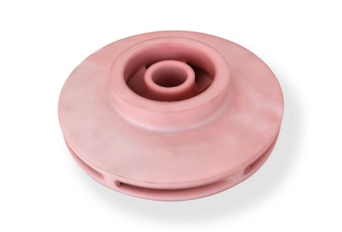
If you’ve ever worked with PTFE—that remarkable, slippery, chemically inert material used in everything from non-stick pans to aerospace seals—you know its performance is legendary. But you’ve also likely hit a wall when trying to prototype or manufacture complex PTFE parts using traditional methods. Machining can be wasteful for intricate designs, and molding requires expensive tooling.
Key takeaways
- So, if FDM is out, what works? The successful methods avoid trying to fully melt PTFE in an open environment.
- Even with SLS or SLM, you’ll face hurdles. Here’s how experts tackle the most frequent issues.
- 3D printing isn’t always the answer. For many projects, traditional methods are more cost-effective or provide superior properties.
- 3D printing PTFE is a reality, but it’s a specialized, high-end manufacturing technique, not a desktop hobby.
Why Is PTFE So Difficult to 3D Print?
PTFE’s incredible properties are a double-edged sword. The very characteristics that make it valuable also make it a nightmare for conventional 3D printing processes like Fused Deposition Modeling (FDM). Let’s break down the core material challenges.
What Makes PTFE’s Thermal Behavior So Problematic?
Imagine trying to melt a material that starts to break down before it even becomes fully liquid. That’s the PTFE paradox. Its extremely high melting point (around 342°C / 648°F) sits dangerously close to its decomposition temperature (starting at about 260°C / 500°F). In an FDM printer, the hotend must melt the filament to extrude it. With PTFE, by the time you reach the melting point, the material is already degrading, releasing toxic fumes like perfluoroisobutylene (PFIB). This isn’t just a print quality issue—it’s a serious safety hazard.
Furthermore, PTFE has exceptionally low thermal conductivity. Heat doesn’t spread evenly through the material. This leads to inconsistent sintering or melting in powder-based processes, causing weak spots. Its poor thermal stability also means it expands and contracts significantly with temperature changes. During printing, uneven cooling creates internal stresses, resulting in warping, cracking, or part shrinkage of 1-3%—a major headache for dimensional accuracy.
How Does PTFE’s “Non-Stick” Nature Work Against It?
The legendary low coefficient of friction and low surface energy that make PTFE so slippery and chemically inert are major obstacles in 3D printing. These properties mean PTFE doesn’t bond to itself easily. In a layer-by-layer process, this translates to weak interlayer adhesion and delamination. The printed part can become brittle and fail structurally, lacking the strength of a solid, molded PTFE component.
| Material Property | Impact on 3D Printing | Consequence for the User |
|---|---|---|
| High Melt Temp / Low Decomp Temp | Material degrades before proper melting in FDM. | FDM printing is impossible & unsafe. Toxic fumes released. |
| Low Thermal Conductivity | Heat distributes unevenly during sintering/melting. | Inconsistent part density and potential weak points. |
| High Thermal Expansion/Shrinkage | Material warps and cracks as it cools. | Dimensional inaccuracy and failed prints. |
| Low Surface Energy | Layers do not adhere to each other well. | Poor mechanical strength and part delamination. |
What Are the Viable 3D Printing Technologies for PTFE?
So, if FDM is out, what works? The successful methods avoid trying to fully melt PTFE in an open environment. Instead, they use precise, controlled heat in a powder bed. Here are the two leading technologies.
Is Selective Laser Sintering (SLS) the Go-To Method?
SLS is currently the most accessible and commonly used method for 3D printing PTFE. It uses a low-power laser (typically 100-300W) to scan over a thin layer of fine PTFE powder. The laser heats the powder particles just to a point where their surfaces soften and fuse (sinter) together, but crucially, it stays below the material’s melting point (operating around 240-250°C). This happens inside a nitrogen-purged chamber to prevent oxidation and degradation.
- Key Advantages: Avoids decomposition, reduces thermal stress, and is excellent for complex geometries like internal channels, lattice structures, and thin walls that are impossible to machine.
- The Trade-off: SLS parts are somewhat porous, achieving about 90-95% density compared to molded PTFE. This can slightly reduce mechanical and chemical resistance properties.
Can Selective Laser Melting (SLM) Deliver Denser Parts?
SLM takes it a step further by using a higher-power laser (500-800W) to fully melt the PTFE powder in tiny, localized spots. The trick is the precise control and speed; the laser hits a small area so briefly that the surrounding powder remains cool, keeping the overall part temperature low. The molten pool then solidifies rapidly.
- Key Advantages: The result is a much denser part (95-98% density) with better mechanical strength—retaining roughly 85-90% of the tensile strength of compression-molded PTFE.
- The Trade-off: This process is far more finicky. It requires extremely precise parameter tuning (laser power, speed, spot size) to avoid decomposition. The equipment cost is significantly higher (often $500k+), making it less common than SLS for PTFE specifically.
| Technology | Key Principle for PTFE | Best For | Considerations |
|---|---|---|---|
| SLS | Laser sinters powder below melting point. | Complex, functional prototypes and parts where ultimate density isn’t critical. | Lower density than molding. More accessible. |
| SLM | Laser fully melts powder in micro-spots. | High-performance, dense parts needing near-molded strength. | Very high cost, complex process control. |
How Do We Solve Common PTFE 3D Printing Problems?
Even with SLS or SLM, you’ll face hurdles. Here’s how experts tackle the most frequent issues.
Problem 1: How Do We Stop PTFE Parts from Warping and Shrinking?
The 1-3% shrinkage is a fact of life, but it can be managed.
- Solution: Controlled, Slow Cooling. Using a heated build chamber maintained at 120-150°C after printing dramatically reduces warping. This slow cooling rate minimizes the rapid crystallization that causes internal stress.
- Solution: Optimized Layer Parameters. Printing with thinner layers (20-30 microns) allows heat to distribute more evenly, reducing the temperature gradient between the hot new layer and the cooler solidified part below.
Problem 2: How Do We Handle PTFE Powder’s Poor Flowability?
PTFE powder is notoriously fluffy and doesn’t spread evenly like nylon or metal powder.
- Solution: Powder Conditioning. Mixing in a tiny amount (1-2%) of a flow aid like fumed silica dramatically improves how the powder spreads, leading to consistent layers.
- Solution: Advanced Recoater Systems. Some industrial printers use a vibrating or rolling recoater arm instead of a simple blade to gently and uniformly distribute the tricky PTFE powder.
Problem 3: How Can We Improve Weak Layer Bonding?
To combat PTFE’s natural reluctance to stick to itself, we can intervene during or after printing.
- In-Process Solution: Composite Powders. Blending the PTFE powder with small amounts of compatible fluoropolymers (like PFA) or ceramic nanoparticles (e.g., alumina) can create “binding sites” that enhance interlayer adhesion without sacrificing key properties.
- Post-Process Solution: Hot Isostatic Pressing (HIP). This is the gold standard for boosting strength. The printed part is placed in a chamber, heated to just below its decomposition point (280-300°C), and subjected to high isostatic gas pressure (10-20 MPa) from all sides. This process densifies the part, closes pores, and fuses layers together, bringing strength close to 95% of molded PTFE.
Where Does 3D Printed PTFE Shine? (Real-World Applications)
This isn’t just a lab curiosity. 3D printed PTFE solves real problems in industries where its unique properties are non-negotiable and part geometries are complex.
- Chemical Processing & Industrial Manufacturing: This is a prime application. Imagine a custom, corrosion-resistant valve liner for a unique reactor setup, or a complex-seal for aggressive chemical pumps. 3D printing allows for these one-off or low-volume custom parts without the cost of machining from a solid block, saving significant material and time.
- Medical & Life Sciences: PTFE is biocompatible and inert, making it FDA-approved for many applications. 3D printing enables patient-specific catheters with customized tip geometries or complex fluidic channels for lab-on-a-chip devices that require absolute chemical inertness to avoid sample contamination.
- Aerospace & Defense: The need for lightweight, high-performance parts is critical. 3D printed PTFE can create complex, weight-saving lattice structures for thermal or electrical insulation, or integrated gaskets and seals for fuel systems that can withstand extreme temperatures from -200°C to 260°C.
- Semiconductor Manufacturing: In the ultra-clean, aggressive chemical environments of wafer fabrication, PTFE is king for components like gas line fittings, wafer carriers, and pump parts. 3D printing facilitates rapid iteration of these high-value, low-volume components.
What Are the Alternatives to 3D Printing PTFE?
3D printing isn’t always the answer. For many projects, traditional methods are more cost-effective or provide superior properties.
- Compression Molding: The industry standard for high-volume PTFE parts. It produces near-theoretical density (98%+) and excellent mechanical properties. It’s ideal for simple shapes like gaskets, seals, and sheets in large batches.
- CNC Machining: Starting from a sintered PTFE rod or sheet, CNC machining is perfect for low-volume, high-precision parts. It avoids all heat-related issues and is often more economical for simpler geometries where material waste is minimal.
- Using a PTFE-Like Alternative (e.g., PCTFE or FEP): Some fluoropolymers are easier to process. For instance, PCTFE (Polychlorotrifluoroethylene) has similar chemical resistance but can be processed on modified FDM printers at lower temperatures, offering a more accessible prototyping path for some applications.
How to write a spec that gets priced correctly
A drawing is a contract. If it leaves a number open, the shop fills that number in with its own default. The default is rarely the one you had in mind. Put these five lines on every RFQ and most of the back-and-forth disappears before it starts.
- File format and units, with the model exported in millimetres
- Process and material grade, not a trade name
- Critical features and the tolerance each one needs
- Surface finish and the faces it applies to
- Quantity for the pilot build and for the year
The point is not paperwork. Each line removes a decision the shop would otherwise make for you. A complete RFQ comes back priced. An incomplete one comes back guessed.
What actually drives the price
Buyers usually push on material because it is the line they can see. In practice the material is rarely the biggest number on a quote. These five lines decide most of it:
- build volume and orientation
- layer height and support structure
- material grade and colour
- post-processing and hand finishing
- quantity per build plate
Ask for the quote split by line. A supplier who cannot break it down is guessing, and you will pay for the guess. The line you can usually renegotiate is the tolerance band, not the raw material.
Problems you will meet, and the fix
Every process has a failure mode it prefers. The same four show up again and again on this kind of work, and none of them are mysteries once you know what to look for.
- Warping on long flat faces where the part lifts off the plate
- Layer lines showing through a cosmetic surface
- Support scars on a mating face nobody flagged
- Dimensional drift on thin walls after cooling
Catch the fault on the first part, not the hundredth. A first-article check costs an hour. A bad batch costs the whole order. Write the check into the purchase order so nobody has to remember it.
What to check on the first article
The first article is the cheapest inspection you will ever buy. Use it properly and the rest of the run becomes boring, which is exactly what you want.
- Every dimension on the drawing, with the measured value written beside it.
- The material certificate, matched to the heat or lot number on the parts.
- The finish against the sample you approved, under the same light.
- Fit against the mating part, assembled rather than measured.
- Packaging, because parts that arrive damaged were never in tolerance.
Check in this order: datums, then mating features, then cosmetic faces. If the datums are wrong, every number after them is noise. Keep the report on file. When a problem shows up in month six, that document is the only thing that tells you what changed.
How to compare two quotes fairly
Two numbers are not comparable unless the scope matches. Line them up before you decide, because a low number with three gaps is not a low number.
Same drawing, same material, same finish, same inspection. Anything else is a different job wearing the same part number. Then look at what each quote leaves out. Freight, packaging, certificates and tooling are the usual gaps.
Ask each supplier to state their assumptions in writing. The one who does is usually the one who has run the process before.
Final Summary: Is 3D Printing PTFE Right for You?
3D printing PTFE is a reality, but it’s a specialized, high-end manufacturing technique, not a desktop hobby. Technologies like SLS and SLM have overcome the fundamental thermal challenges by using precise, controlled heating in a powder bed.
Choose 3D printing PTFE when:
- Your design features complex internal geometries, lattices, or thin walls.
- You need low-volume or one-off custom parts and the lead time/cost for machining or molding is prohibitive.
- Rapid prototyping of a high-performance PTFE component is necessary for validation.
Consider traditional methods (machining/molding) when:
- Your part design is relatively simple.
- You require the absolute maximum mechanical strength and density.
- You are producing high volumes, where unit cost is the primary driver.
The decision hinges on the classic trade-off between design complexity, production volume, performance requirements, and budget.
FAQ: Your PTFE 3D Printing Questions Answered
Q: How strong is 3D printed PTFE compared to molded PTFE?
A: SLS-printed PTFE typically achieves 80-90% of the tensile strength of molded PTFE. With post-processing like Hot Isostatic Pressing (HIP), this can be improved to 90-95%, which is sufficient for a vast range of functional applications.
Q: Is it safe to 3D print PTFE at home or in a standard workshop?
A: Absolutely not. Attempting to print pure PTFE on any standard FDM or open-bed printer is dangerous. The decomposition releases highly toxic fumes. Professional SLS/SLM systems are fully sealed, use inert gas environments, and have advanced filtration to make the process safe.
Q: When does 3D printing PTFE become cost-effective compared to machining?
A: For a simple bracket, machining will almost always be cheaper. The breakeven point for complexity comes with parts featuring internal channels, undercuts, or complex contours. Machining these requires multiple setups and generates up to 70% material waste, while 3D printing uses only the powder needed for the part, often making it 20-40% more cost-effective for such designs.
Our solution for 3D Print PTFE
YiguProto runs 3D printing in house, from a single prototype to a production batch. We quote the process, the material and the finish as separate lines, so you can see where the money goes instead of arguing with one number.
Send a STEP file or a drawing and you get a DFM report in one to two business days. It flags the features that add cost and the features that will not hold tolerance on the process you picked.
Every order ships with an inspection report on the features you call out. If a part misses, we make it again. Ready to price a part? Start with a free quote and DFM review, or read more about our 3D printing. You can also talk to an engineer before you commit to a drawing.
FAQ about 3D Print PTFE
How much does 3D Print PTFE cost?
Price comes from five lines: material, machine or tool time, setup, finishing and inspection. The material itself is usually the smallest of them. Send a drawing and we will split the quote so you can see which line is doing the damage.
What is 3D Print PTFE used for?
3D Print PTFE turns up wherever the part has to do a real job at a predictable cost: brackets, housings, fixtures, covers and the fittings that hold them together. The honest test is whether the properties match the load and the environment, not whether the material is fashionable.
What tolerance can you hold on 3D Print PTFE?
The working default is ±0.1 mm on small features, ±0.3% on long spans. Tighter than that the process changes and so does the price, because every step tighter adds inspection time. Call out only the faces that mate with something else and leave the rest on the general tolerance.
How long does a first article take?
Usually a few business days once the drawing is frozen, and longer if tooling is involved. The date we give you is the date we confirm in writing, not the date we hope for.
What material should I specify?
Specify by standard, not by trade name. A trade name can change under you between two orders; a standard number cannot. Then add the one property that actually decides the part, whether that is strength, heat resistance or chemical exposure.
Is there a minimum order quantity?
No hard minimum. One part is fine. What changes with volume is which costs dominate, so a single unit is priced mostly on setup and a thousand units are priced mostly on cycle time and material.
The short version
3D Print PTFE rewards the buyer who reads the data sheet and the drawing together. Pick the option for the property that matters, not for the price per kilo.
Tighten only what mates. Test a sample before the run. Then let the process do the rest.