
Blogs
Copper 3D Printing Services
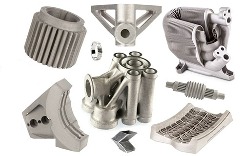
Transform your high-conductivity projects with Copper 3D Printing—the perfect blend of additive manufacturing innovation and copper’s unmatched electrical/thermal performance. From intricate electronics components to aerospace heat exchangers, our solutions deliver complex geometries, rapid prototyping, and cost-effective customization.
Key takeaways
- At our shop, our Copper 3D Printing capabilities are engineered to meet the strict demands of industries from electronics to aerospace.
- Copper 3D Printing is an advanced metal 3D printing process that uses additive manufacturing principles to build parts layer by layer from copper feedstock (typically powder).
- Our Copper 3D Printing process is a structured, optimized workflow that addresses copper’s high thermal conductivity (which can dissipate heat during printing) to ensure reliability:
- Our Copper 3D Printing case studies showcase how we’ve helped clients overcome challenges and achieve better results than traditional methods:

Our Capabilities: Delivering Copper 3D Printing Excellence
At our shop, our Copper 3D Printing capabilities are engineered to meet the strict demands of industries from electronics to aerospace. We combine advanced equipment with deep technical expertise to deliver consistent, high-quality results:
- High-Precision Printing: Our machines (e.g., EOS M 300-4, SLM Solutions 500) achieve tight tolerances (as low as ±0.05mm) and part densities up to 99.5%—critical for electronics components requiring precise fits.
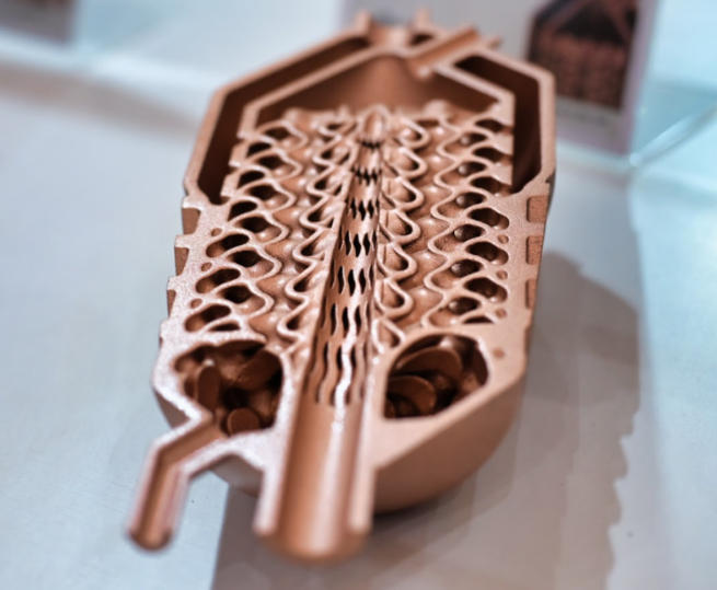
- Complex Geometries: We print intricate designs (e.g., internal cooling channels, lattice structures) that are impossible with traditional machining—ideal for optimizing heat dissipation in electronics.
- Custom Copper Parts: Whether you need a custom heat sink for a medical device or a complex connector for telecommunications, we tailor every step (material selection, post-processing) to your unique needs.
- Rapid Prototyping: Turn digital designs into physical copper prototypes in 3–5 days—accelerating product development by 60% vs. traditional casting.
- Industrial Capabilities: Scale up to 10,000+ parts monthly with automated workflows—our process ensures consistent quality, even for high-volume electronics components.
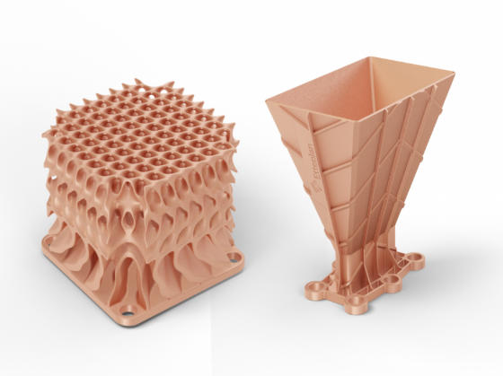
Table: Our Copper 3D Printing Capabilities vs. Industry Averages
| Capability | our shop Performance | Industry Average |
| Max Build Volume | 300mm × 300mm × 400mm | 250mm × 250mm × 300mm |
| Prototyping Lead Time | 3–5 days | 7–10 days |
| Production Capacity | Up to 6,000 parts/week | Up to 2,500 parts/week |
| Part Density | 99.2–99.5% | 95–98% |
| Electrical Conductivity Retention | 92–95% (vs. pure copper) | 85–90% |
What Is Copper 3D Printing?
Copper 3D Printing is an advanced metal 3D printing process that uses additive manufacturing principles to build parts layer by layer from copper feedstock (typically powder). Unlike traditional methods (e.g., casting, machining), it focuses on layer-by-layer fabrication—adding material only where needed to create functional parts from digital designs.
At its core, this technology leverages copper’s unique properties: exceptional electrical conductivity (96% of pure silver’s conductivity) and thermal conductivity (401 W/m·K)—making it indispensable for applications where heat dissipation or electrical transfer is critical. The definition and scope of copper 3D printing includes both pure copper and copper alloys (e.g., brass, bronze), each tailored to specific industry needs.
Key Basics of Copper 3D Printing:
| Term | Description | Role in the Process |
| Pure Copper | 99.9% pure copper powder, high conductivity | Electronics (circuit boards, connectors), thermal management parts |
| Copper Alloys | Blends like brass (copper + zinc) or bronze (copper + tin), balanced strength/conductivity | Automotive components, consumer goods |
| Technology Overview | Relies on high-energy processes (laser/electron beam) to melt copper’s high-melting-point (1,085°C) powder | Ensures dense, functional parts with minimal porosity |
Process: The Step-by-Step Workflow for Copper 3D Printing
Our Copper 3D Printing process is a structured, optimized workflow that addresses copper’s high thermal conductivity (which can dissipate heat during printing) to ensure reliability:
- Pre-Processing:
- Design Optimization: Our team reviews your CAD model to optimize it for copper—e.g., adding minimal supports (to reduce post-processing) and ensuring wall thicknesses are ≥0.3mm (to avoid print failures).
- Powder Preparation: We use spherical copper powder (15–45μm particle size) with high flowability—critical for uniform copper powder bed fusion.
- Printing Phase:
- The most common techniques are Selective Laser Melting (SLM) and Electron Beam Melting (EBM). SLM uses a high-power laser (500–1,000W) to melt copper powder, while EBM uses an electron beam—both create dense parts by overcoming copper’s heat dissipation challenge.
- For lower-cost, high-volume parts, we use binder jetting—binding copper powder with a liquid binder, then sintering it post-print to densify.
- Post-Processing Techniques:
- Support Removal: We carefully remove metal supports via machining or wire EDM to avoid damaging the part.
- Sintering (for binder jetting): Parts are heated to 900–1,000°C to fuse copper particles, increasing density and conductivity.
- Heat Treatment: Annealing (600–800°C) reduces internal stress and restores conductivity (critical for electronics parts).
- Quality Control: Every part is inspected with:
- X-ray CT scans to check for internal porosity.
- Coordinate measuring machines (CMMs) to verify dimensional accuracy.
Conductivity testing (using a eddy current tester) to ensure electrical/thermal performance meets specs.
How to write a spec that gets priced correctly
A drawing is a contract. If it leaves a number open, the shop fills that number in with its own default. The default is rarely the one you had in mind. Put these five lines on every RFQ and most of the back-and-forth disappears before it starts.
- A model and a drawing that agree
- Material by standard number
- Tolerance only where it mates
- Finish and the faces it applies to
- Quantity and required date
The point is not paperwork. Each line removes a decision the shop would otherwise make for you. A complete RFQ comes back priced. An incomplete one comes back guessed.
What actually drives the price
Buyers usually push on material because it is the line they can see. In practice the material is rarely the biggest number on a quote. These five lines decide most of it:
- process choice
- material
- tolerance band
- finish
- volume
Ask for the quote split by line. A supplier who cannot break it down is guessing, and you will pay for the guess. The line you can usually renegotiate is the tolerance band, not the raw material.
Problems you will meet, and the fix
Every process has a failure mode it prefers. The same four show up again and again on this kind of work, and none of them are mysteries once you know what to look for.
- A drawing that contradicts the model
- A tolerance with no datum
- A cosmetic callout with no approved sample
- A quote compared against a different scope
Catch the fault on the first part, not the hundredth. A first-article check costs an hour. A bad batch costs the whole order. Write the check into the purchase order so nobody has to remember it.
What to check on the first article
The first article is the cheapest inspection you will ever buy. Use it properly and the rest of the run becomes boring, which is exactly what you want.
- Every dimension on the drawing, with the measured value written beside it.
- The material certificate, matched to the heat or lot number on the parts.
- The finish against the sample you approved, under the same light.
- Fit against the mating part, assembled rather than measured.
- Packaging, because parts that arrive damaged were never in tolerance.
Check in this order: datums, then mating features, then cosmetic faces. If the datums are wrong, every number after them is noise. Keep the report on file. When a problem shows up in month six, that document is the only thing that tells you what changed.
How to compare two quotes fairly
Two numbers are not comparable unless the scope matches. Line them up before you decide, because a low number with three gaps is not a low number.
Same drawing, same material, same finish, same inspection. Anything else is a different job wearing the same part number. Then look at what each quote leaves out. Freight, packaging, certificates and tooling are the usual gaps.
Ask each supplier to state their assumptions in writing. The one who does is usually the one who has run the process before.
Scaling from one part to a batch
The first part teaches you the process. The hundredth teaches you the process cost.
Watch three things as volume grows: setup amortisation, tool wear, and how much hand work the finish still needs. If the unit price barely moves between ten and a hundred, the cost sits in material or in hand work, not in setup. Ask which, because only one of them is negotiable.
Lead time behaves the same way. A one-off is scheduled around other jobs. A repeat order is scheduled around your forecast. Give the shop a forecast and the lead time gets shorter, not longer.
How to read a supplier's quote
A quote is a short document with a long shadow. Four things in it decide whether the job runs smoothly, and only one of them is the price.
- The scope line. It should name the process, the material and the finish, not just the part.
- The tolerance basis. General tolerance or the drawing, and which standard it follows.
- The exclusions. Tooling, freight, certificates and inspection are the usual omissions.
- The validity date. Material prices move, and an open-ended quote is a promise nobody can keep.
Read the exclusions before you read the total. A quote that leaves out tooling is not cheaper. It is a quote for a different job.
What to send with the first order
The first order sets the pattern for every order after it. Send a complete package once and the shop files it, and the second order takes a fraction of the time.
- A STEP or native model plus a PDF drawing carrying the same revision letter.
- The material callout by standard number, not by trade name.
- The finish and the exact faces it applies to.
- Any test the part must pass: fit, seal, drop, salt spray, dielectric.
- A contact who can answer a question inside one working day.
Then write down what was agreed. An email that confirms the material, the finish and the date is worth more than a longer purchase order that leaves them open.
When this is the wrong choice
A good supplier tells you when the process does not fit. These are the cases where we say so.
- The volume is so low that setup costs more than the parts are worth.
- The tolerance is tighter than the process can hold without a second operation.
- The geometry cannot be made without a tool feature that will not pay back.
- The material you need is not available in the form the process requires.
- The schedule is shorter than the tooling or setup time, and nobody has said so yet.
None of these are refusals. They are reasons to look at a different route, and the earlier that conversation happens the cheaper it is. The most expensive mistake in manufacturing is a process chosen before the question was understood.
Planning the ramp from prototype to production
The gap between one good part and a thousand identical ones is a plan, not a machine. Three decisions close it.
First, freeze the design. Every change after tooling starts is a re-cut, and re-cuts are where schedules go. Second, decide the inspection level. A prototype is checked by eye; a production part is checked against a report. Third, agree the change process in writing, including who pays for it.
Write the ramp down as dates and owners, not as intentions. A ramp plan with three names and three dates is worth more than a page of good intentions.
What documentation to expect
Paperwork is not bureaucracy when a part fails at the customer. It is the only record of what was agreed. A normal shipment should carry four documents.
- A dimensional report covering every callout on the drawing.
- A material certificate traceable to the heat or lot number.
- A finish or coating certificate where the specification requires one.
- A packing list that matches the carton labels.
If a supplier cannot produce these on request, they are not running a controlled process. Ask for one sample set before you place the first order and you will know exactly what you are buying.
How to handle a change after the order
Changes happen. What matters is whether the change is priced, scheduled and recorded, or absorbed quietly and discovered later.
Send the change as a new revision, not as a note in an email. Ask for three answers in writing: what it costs, what it does to the date, and what happens to material or tooling already committed. Then decide.
A change without a revision number is a rumour. The shop will build what it has on file, and both sides will be right and unhappy at the same time.
How the work actually runs, step by step
Most buyers see two numbers: a price and a date. Between them sits a sequence that decides both. On manufacturing work it looks like this.
- File review. The model and the drawing are checked against each other. Where they disagree, the shop stops and asks, because guessing is how scrap gets made.
- DFM feedback. The features that add cost and the features that will not hold tolerance are listed. This is the cheapest hour in the whole project.
- Setup or tooling. Fixtures, programs or a tool are built. Everything downstream inherits the quality of this step.
- First article. One part is made and measured against the drawing before anything else runs. Nothing is signed until it passes.
- Production. The run goes ahead with the parameters that produced the approved first article, not with new ones.
- Inspection and packing. The callouts are measured, the certificate is matched, and the parts are packed so they arrive in the condition they left in.
Ask any supplier to walk you through these six steps on your part. The answers tell you more about the shop than the price does.
Case Studies: Copper 3D Printing in Action
Our Copper 3D Printing case studies showcase how we’ve helped clients overcome challenges and achieve better results than traditional methods:
Case Study 1: Electronics Heat Sink
- Client: A global electronics manufacturer.
- Challenge: Need a compact heat sink for a high-performance GPU that dissipates 200W of heat (traditional heat sinks were too bulky and inefficient).
- Solution: SLM-printed pure copper heat sink with internal lattice cooling channels—optimized for maximum surface area.
- Results:
- 30% better heat dissipation vs. traditional heat sinks (GPU temperature reduced by 15°C).
- 40% weight reduction (from 150g to 90g).
- Lead time cut to 4 days (vs. 3 weeks for machined heat sinks).
Case Study 2: Aerospace Heat Exchanger
- Client: A leading aircraft manufacturer.
- Challenge: Reduce the weight of a cabin heat exchanger (traditional copper-brass exchanger weighed 2.2kg, increasing fuel consumption).
- Solution: EBM-printed copper-nickel heat exchanger with lightweight lattice structure.
- Results:
- 50% weight reduction (1.1kg vs. 2.2kg).
- 20% improved thermal efficiency (faster cabin temperature regulation).
- 35% cost savings vs. brazed traditional exchangers.
Case Study 3: EV Battery Connector
- Client: An electric vehicle startup.
- Challenge: Create a high-conductivity battery connector that fits tight EV battery pack dimensions (traditional machined connectors had poor fit and high resistance).
- Solution: Binder jetted pure copper connector—sintered for density, then silver-plated for corrosion resistance.
- Results:
- 95% conductivity retention (vs. 85% for machined connectors).
- 100% fit rate (no rework needed for battery packs).
40% cost savings for high-volume production (10,000+ units/month).
Our solution for Copper 3D Printing Services
YiguProto runs custom manufacturing in house, from a single prototype to a production batch. We quote the process, the material and the finish as separate lines, so you can see where the money goes instead of arguing with one number.
Send a STEP file or a drawing and you get a DFM report in one to two business days. It flags the features that add cost and the features that will not hold tolerance on the process you picked.
Every order ships with an inspection report on the features you call out. If a part misses, we make it again. Ready to price a part? Start with a free quote and DFM review, or read more about our custom manufacturing. You can also talk to an engineer before you commit to a drawing.
FAQ about Copper 3D Printing Services
Does 3D-printed copper retain the same electrical and thermal conductivity as traditional copper parts?
Yes—our 3D-printed copper retains 92–95% of pure copper’s electrical conductivity (58 MS/m) and thermal conductivity (401 W/m·K), which is higher than industry averages (85–90%). This is achieved through optimized printing parameters (e.g., high laser power for SLM) and post-processing (e.g., annealing to reduce internal stress). For applications requiring maximum conductivity (e.g., high-frequency electronics), we offer silver-plated 3D-printed copper parts—boosting conductivity to 98% of pure copper.
Can you 3D print large copper parts, like aerospace heat exchangers or industrial valves?
Absolutely! Our largest EBM machines handle copper parts up to 300mm × 300mm × 400mm—sufficient for most aerospace heat exchangers and industrial valves. For even larger parts (e.g., 1m+ industrial pipes), we use hybrid techniques: 3D printing smaller copper sections, then joining them via welding (using copper-compatible fillers) to maintain conductivity and structural integrity. We recently delivered a 600mm × 400mm × 300mm copper heat exchanger for an aerospace client, which met all thermal efficiency and weight requirements.
What is the cost difference between 3D-printed copper parts and traditionally manufactured (cast/machined) copper parts?
The cost depends on volume and complexity:Small batches (1–100 parts): 3D printing is 50–70% cheaper than casting (no expensive tooling) and 30–40% cheaper than machining (less material waste). For example, a custom copper heat sink (100mm × 50mm × 20mm) costs 150–200 via 3D printing vs. 300–400 via machining.High volumes (1,000+ parts): Traditional casting may be cheaper for simple geometries (e.g., brass fittings), but 3D printing remains cost-competitive for complex parts (e.g., lattice-structured heat sinks) due to reduced material waste. We offer volume discounts for 1,000+ parts, bringing costs within 10–15% of casting for most complex designs.
What is Copper 3D Printing Services used for?
Copper 3D Printing Services turns up wherever the part has to do a real job at a predictable cost: brackets, housings, fixtures, covers and the fittings that hold them together. The honest test is whether the properties match the load and the environment, not whether the material is fashionable.
What files do you need in order to quote?
A STEP file plus a PDF drawing that carries the same revision letter. The model carries the geometry and the drawing carries the intent. When the two disagree, the shop picks one, and it is never the one you meant.
How do I compare two quotes fairly?
Match the scope first: same drawing, same material, same finish, same inspection. Then read the exclusions. Freight, tooling and certificates are the usual gaps, and a low number with three gaps is not a low number.
The short version
Copper 3D Printing Services rewards the buyer who reads the data sheet and the drawing together. Pick the option for the property that matters, not for the price per kilo.
Tighten only what mates. Test a sample before the run. Then let the process do the rest.