
Injection Molding
Custom Molded Plastic Parts: How Do You Go From Design to Production?
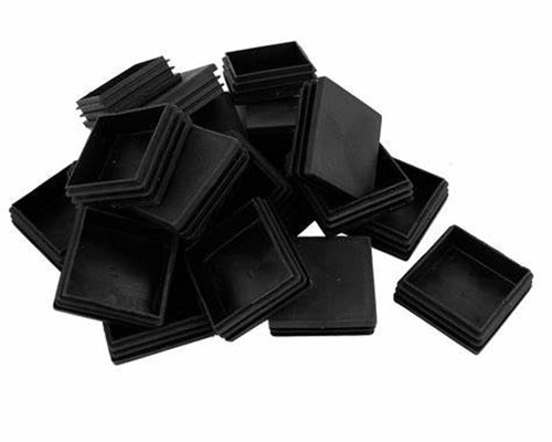
Look around you right now. The device in your hand, the parts in your car, the containers in your kitchen—many of them started as a custom molded plastic part. This manufacturing process is the hidden engine behind modern product development. It turns digital designs into real, working parts on a massive scale. It is the bridge between a great idea and a product ready for the market.
Key takeaways
- Simply put, custom molded plastic parts are components created by shaping melted plastic inside a specific, custom-built mold.
- To manage a project effectively, you need to understand the fundamental workflow. It is a step-by-step journey where each stage builds on the last.
- The mold, also called tooling, is a precision-machined metal block. It contains a cavity in the exact shape of your part.
- Design for Manufacturability (DFM) is the single most important practice for a successful project. It is not just a buzzword.
What Are Custom Molded Plastic Parts?
Simply put, custom molded plastic parts are components created by shaping melted plastic inside a specific, custom-built mold. This is fundamentally different from using off-the-shelf parts or other manufacturing methods.
- Unlike CNC machining, which cuts away material from a solid block, molding forms the part from raw material. Machining is subtractive; molding is additive in the sense that it fills a cavity.
- Unlike 3D printing, which builds parts layer by layer and is ideal for one-off prototypes, molding is designed for repeatability and large-scale production. A single mold can produce millions of identical parts.
This process allows for the creation of components that are precisely tailored to a product’s unique functional and visual needs. It is the foundation of mass production for plastic products.
Why Should You Choose Custom Molding?
Choosing the right manufacturing process is a critical decision. Custom molding offers a powerful combination of benefits that make it the preferred choice for a vast range of applications.
- Design Freedom and Complexity: Molding can produce incredibly detailed shapes, built-in features like snap-fits, and complex curves that would be impossible or extremely expensive to create with any other method.
- Cost-Effectiveness at Scale: Yes, there is an initial investment in the mold. But once that tool is made, the per-unit cost drops dramatically as you make more parts. For runs of thousands or millions, it is almost always the most economical choice.
- Material Variety and Performance: The world of plastics is vast. Custom molding gives you access to thousands of materials, from durable and chemical-resistant to optically clear or rubber-like.
- Consistency and Repeatability: A well-made mold produces parts with extremely high accuracy from the first part to the millionth. This ensures every part meets the same quality standards, which is critical for assembly and product performance.
What Is the End-to-End Workflow for Custom Molding?
To manage a project effectively, you need to understand the fundamental workflow. It is a step-by-step journey where each stage builds on the last. Mistakes in early stages lead to big problems later. Here is the six-stage roadmap.
Stage 1: Initial Concept and Design
This is the beginning. It starts with an idea, which is then translated into a 3D CAD (Computer-Aided Design) model. This digital blueprint defines the part’s exact shape, features, and dimensions. Every detail of the final part starts here.
Stage 2: Material Selection
Based on the part’s job, its performance needs, and your budget, the right plastic is chosen. Will it be a strong, tough ABS for a power tool housing? A flexible polypropylene (PP) for a living hinge? This decision impacts everything.
Stage 3: Mold Design and Creation (Tooling)
This is the most critical and expensive phase. A specialized toolmaker designs and builds the mold, usually from steel or aluminum. The quality of this tool determines the quality of every single part it will ever make. This is the “heart” of the process.
Stage 4: Prototyping and Testing
Before mass production, initial parts (first samples) are made. This is your chance to validate the design, the material, and the mold’s function. You test the form, fit, and function of the actual part.
Stage 5: Mass Production
Once the prototype is approved, the full production run begins. The molding machine runs in a continuous, automated cycle to produce the required quantity of parts.
Stage 6: Quality Control and Finishing
Throughout and after production, parts are inspected to ensure they meet specs. This stage also includes secondary operations like trimming, decorating, or assembly.
Why Is the Mold the Heart of the Process?
The mold, also called tooling, is a precision-machined metal block. It contains a cavity in the exact shape of your part. Hot plastic is forced into this cavity, cools, and becomes your part. This tooling is the biggest upfront investment. Its design is everything.
- Mold Material: Molds are typically made from hardened steel or aluminum. Steel molds are incredibly durable and can last for millions of cycles. They are the standard for high-volume production. Aluminum molds are cheaper and faster to make, but they wear out faster. They are perfect for prototyping or low-volume runs.
- Cavities: A mold can have a single cavity (making one part per cycle) or multiple cavities (making several identical parts at once). Multi-cavity molds boost output but cost more and are more complex.
- Complexity: Features like undercuts (side holes or clips) require moving parts in the mold, like slides or lifters. This adds cost and lead time.
What Is Design for Manufacturability and Why Is It Critical?
Design for Manufacturability (DFM) is the single most important practice for a successful project. It is not just a buzzword. It is the practice of designing your part so that it is as easy and efficient to manufacture as possible. Ignoring DFM is a direct path to costly redesigns, broken tools, and bad parts.
DFM is a proactive step. You analyze your CAD model from the perspective of the molding process. The goal is to find and fix problems before any steel is cut for the mold. A part that looks perfect on a screen may be impossible to mold or may come out warped and weak. DFM bridges the gap between the digital design and physical reality.
What Are the Key DFM Principles?
Understanding the “why” behind each rule helps you create better designs.
- Uniform Wall Thickness: This is the most critical rule. Walls should be as uniform as possible. Thick sections cool slower than thin sections, causing uneven shrinkage. This creates internal stress, leading to sink marks (surface dents) and warping (bending).
- Draft Angles: For a part to release cleanly from the mold, its vertical walls must have a slight taper, or draft. Without it, the part will drag and scrape against the mold. A minimum of 1 to 2 degrees of draft is the standard rule.
- Radii and Corners: Sharp internal corners are stress points. They concentrate force and can cause the part to crack. They also restrict the flow of plastic. Adding a smooth radius spreads out stress and helps the plastic flow, making the part much stronger.
- Undercuts: An undercut is any feature that prevents the part from being pulled straight out of the mold, like a side hole. Undercuts require complex moving parts in the mold (side-actions). These add significant cost and complexity. A key DFM task is to ask: “Can I design this without an undercut?”
- Ribs and Bosses: Ribs add strength without making the whole wall thicker. Bosses are for screw holes. Both must be designed carefully. A common rule is that the thickness of a rib or boss wall should be about 60% of the main wall thickness it attaches to. If it is thicker, it will create a sink mark on the opposite side.
A Practical DFM Checklist
Here is a simple checklist to run through with your design.
| Common Mistake | Best Practice / Solution |
|---|---|
| Walls of different thickness | Aim for uniform thickness. If you must change, make the transition gradual. |
| Zero draft on vertical walls | Add a minimum of 1-2 degrees of draft to all surfaces parallel to the mold opening. |
| Sharp internal corners | Add a radius that is at least half (0.5x) the wall thickness. |
| Complex undercuts | Ask: Can I avoid this? If not, plan for the added mold cost. |
| Ribs and bosses too thick | Follow the 60% rule. Keep them thinner than the main wall. |
How Do You Choose the Right Material?
Selecting the right plastic is as critical as the design itself. The material determines strength, appearance, lifespan, and cost. With thousands of options, you need a systematic way to choose.
What Factors Should You Consider?
Before looking at specific materials, define your part’s needs.
- Mechanical Properties: Does it need to be strong (high tensile strength)? Stiff? Flexible? Will it be dropped (impact resistance)?
- Environmental Resistance: Will it be in the sun (UV resistance)? Will it touch chemicals or oils?
- Thermal Properties: Will it get hot or cold? What is its operating temperature range?
- Regulatory Requirements: Does it need to be food-safe (FDA)? Flame-retardant (UL)? Safe for medical use (biocompatible)?
- Visual Appeal: Does it need to be transparent? A specific color? A glossy or textured finish?
- Cost: Material prices vary widely, from low-cost commodity plastics to expensive high-performance ones.
A Quick Guide to Common Plastics
| Material | Common Use Cases | Key Characteristics | Relative Cost |
|---|---|---|---|
| ABS | Consumer electronics, toys, housings | Good impact strength, stiff, easy to mold, good surface finish | Low to Medium |
| Polypropylene (PP) | Living hinges, food containers, automotive | Excellent chemical resistance, flexible, very low cost, lightweight | Low |
| Polycarbonate (PC) | Safety shields, lenses, power tool housings | Very high impact strength, transparent, good heat resistance | Medium to High |
| Nylon (PA 6/6) | Gears, bearings, structural parts | High strength, excellent wear resistance, high melting point | Medium |
| HDPE | Bottles, cutting boards, chemical tanks | Excellent chemical resistance, tough, low cost | Low |
| TPE/TPU | Soft grips, seals, overmolded parts | Rubber-like flexibility, good grip, durable | Medium to High |
| Acrylic (PMMA) | Lenses, displays, light covers | Excellent optical clarity, scratch-resistant, UV stable | Medium |
What Are the Main Molding Techniques?
While injection molding is the most common, it is not the only option. The shape of your part determines the best process.
Injection Molding
This is the workhorse of the industry for high-volume, solid parts.
- How it Works: Plastic pellets are melted and shot under high pressure into a closed mold. The part cools and is ejected. The cycle repeats in seconds.
- Best For: High-volume production of complex, solid parts like enclosures, automotive components, and gears.
Blow Molding
If your part is hollow, this is likely the right process.
- How it Works: A hot tube of plastic (a parison) is placed in a mold. Air is blown into it, inflating it like a balloon until it presses against the mold walls.
- Best For: Bottles, containers, tanks, and ducts.
Rotational Molding
This is for very large, hollow, and durable parts.
- How it Works: Plastic powder is placed in a mold. The mold is heated and rotated in two directions. The melting plastic coats the inside of the mold, building up a uniform wall thickness.
- Best For: Large tanks, kayaks, playground equipment, and coolers.
How to write a spec that gets priced correctly
A drawing is a contract. If it leaves a number open, the shop fills that number in with its own default. The default is rarely the one you had in mind. Put these five lines on every RFQ and most of the back-and-forth disappears before it starts.
- STEP file plus a 2D drawing with the revision letter
- Resin grade with the standard number, not the trade name
- Draft angle on every wall that runs along the pull
- Texture and the SPI grade it maps to
- Annual volume and the launch quantity
The point is not paperwork. Each line removes a decision the shop would otherwise make for you. A complete RFQ comes back priced. An incomplete one comes back guessed.
What actually drives the price
Buyers usually push on material because it is the line they can see. In practice the material is rarely the biggest number on a quote. These five lines decide most of it:
- tool steel grade and cavity count
- part weight and wall thickness
- cycle time
- surface texture and SPI grade
- resin grade and colour
Ask for the quote split by line. A supplier who cannot break it down is guessing, and you will pay for the guess. The line you can usually renegotiate is the tolerance band, not the raw material.
Problems you will meet, and the fix
Every process has a failure mode it prefers. The same four show up again and again on this kind of work, and none of them are mysteries once you know what to look for.
- Short shots at the end of flow on a thin wall
- Sink marks opposite a thick rib
- Warp from uneven cooling on a mixed-wall part
- Flash on a parting line that has worn in
Catch the fault on the first part, not the hundredth. A first-article check costs an hour. A bad batch costs the whole order. Write the check into the purchase order so nobody has to remember it.
Why Is Prototyping and Testing So Important?
The prototyping stage is your final reality check. It is your chance to hold a physical part before you spend tens of thousands on a production mold. It is where you catch errors that are cheap to fix now, but catastrophic to fix later. We have seen countless projects saved by a thorough prototype phase.
The main goal is to test form, fit, and function. A part that looks perfect on a screen might feel flimsy in your hand. An assembly issue that was invisible in CAD becomes obvious when you try to snap two parts together.
A Prototype Validation Checklist
Use this checklist when you get your prototype.
- Form and Ergonomics: Does it look and feel right? Is it comfortable to hold? This is your first real user experience.
- Fit and Assembly: Does it connect correctly with other parts? Check clearances. Try assembling and disassembling it a few times.
- Functional Testing: Does it do its job? Test its strength, flexibility, and any moving parts under real-world conditions.
- DFM Review: Look at the physical part for potential molding problems. Do you see a thick area that might cause a sink mark? A sharp corner that could be a stress point?
The journey of creating a custom molded plastic part is complex, but it is manageable. It requires a blend of creative design, engineering discipline, and manufacturing knowledge. Success depends on a few key pillars: a solid, manufacturable design (following DFM principles), the selection of the correct material for the job, and choosing the right molding process for the part’s shape and volume. Navigating these stages can be challenging, but a knowledgeable manufacturing partner can guide you through it, turning your vision into a high-quality, market-ready product.
Our solution for Custom Molded Plastic Parts: How
YiguProto runs injection molding in house, from a single prototype to a production batch. We quote the process, the material and the finish as separate lines, so you can see where the money goes instead of arguing with one number.
Send a STEP file or a drawing and you get a DFM report in one to two business days. It flags the features that add cost and the features that will not hold tolerance on the process you picked.
Every order ships with an inspection report on the features you call out. If a part misses, we make it again. Ready to price a part? Start with a free quote and DFM review, or read more about our injection molding. You can also talk to an engineer before you commit to a drawing.
FAQ about Custom Molded Plastic Parts: How
What files do you need in order to quote?
A STEP file plus a PDF drawing that carries the same revision letter. The model carries the geometry and the drawing carries the intent. When the two disagree, the shop picks one, and it is never the one you meant.
How long does a first article take?
Usually a few business days once the drawing is frozen, and longer if tooling is involved. The date we give you is the date we confirm in writing, not the date we hope for.
How do I compare two quotes fairly?
Match the scope first: same drawing, same material, same finish, same inspection. Then read the exclusions. Freight, tooling and certificates are the usual gaps, and a low number with three gaps is not a low number.
What tolerance can you hold on Custom Molded Plastic Parts: How?
The working default is ±0.1 mm as a working default, ±0.05 mm on critical features. Tighter than that the process changes and so does the price, because every step tighter adds inspection time. Call out only the faces that mate with something else and leave the rest on the general tolerance.
What material should I specify?
Specify by standard, not by trade name. A trade name can change under you between two orders; a standard number cannot. Then add the one property that actually decides the part, whether that is strength, heat resistance or chemical exposure.
Can Custom Molded Plastic Parts: How be made in small quantities?
Yes, and small quantities are where a good supplier earns the next order. Setup dominates the price at low volume, so the cheapest route is usually the one with the fewest operations, not the cheapest material.
The short version
Custom Molded Plastic Parts: How rewards the buyer who reads the data sheet and the drawing together. Pick the option for the property that matters, not for the price per kilo.
Tighten only what mates. Test a sample before the run. Then let the process do the rest.