
3D Printing
How Do You Determine the Ideal Size for 3D Printing Success?
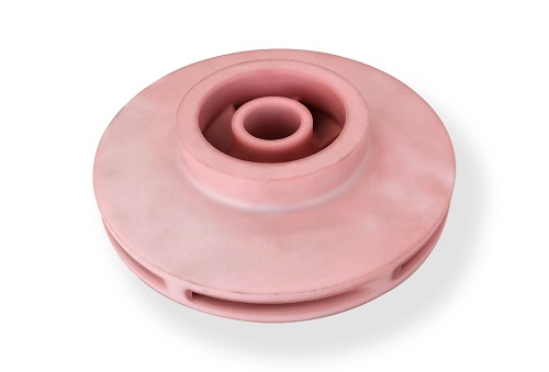
Whether you are an engineer prototyping a high-stress industrial bracket, a hobbyist building a custom drone frame, or an architect presenting a scaled model, “size” is far more than a numerical value in a CAD file. In the world of additive manufacturing, dimensions are a complex interaction between mechanical tolerances, material shrinkage, and printer build volumes.
Key takeaways
- Before you open your design software, you must acknowledge the physical boundaries of your hardware.
- Once you confirm the part fits the plate, the focus shifts to internal sizing: wall thickness, nozzle line width, and mechanical tolerances.
- Not all materials are created equal when it comes to dimensional stability.
- Environmental factors and machine settings act as the final “gatekeepers” of size accuracy.
What Are Your Printer’s Hard Limits?
Before you open your design software, you must acknowledge the physical boundaries of your hardware. The build volume (Length × Width × Height) is the absolute “sandbox” your printer can operate within.
Understanding Build Volume by Technology
Different 3D printing technologies offer vastly different spatial capacities. While FDM (Fused Deposition Modeling) is known for larger, more affordable volumes, SLA (Stereolithography) usually prioritizes high-resolution detail within a smaller footprint.
Table: Comparative Build Volumes and Best Use Cases
| Printer Type | Typical Build Volume (mm) | Technology Strength | Ideal Application |
| FDM | 200³ to 400³ | Scalability | Functional prototypes, large housings |
| SLA/Resin | 150 × 150 × 200 | Micron-level precision | Jewelry, dental, high-detail figurines |
| SLS | 300³ to 600³ | No supports needed | Industrial-grade production, complex gears |
Case Study: The Oversized Drone Frame
A DIY developer recently attempted to print a 300mm racing drone frame on a standard 220mm build plate. Instead of scaling the model down—which would have rendered the electronic mounts useless—they utilized model sectioning. By splitting the frame into two interlocking components with a dove-tail joint, they printed the parts separately. This “modular” approach allowed for a larger-than-machine result without sacrificing the 1:1 scale required for the motors and flight controller.
How Do You Optimize Design for Dimensional Accuracy?
Once you confirm the part fits the plate, the focus shifts to internal sizing: wall thickness, nozzle line width, and mechanical tolerances.
1. The Rule of Wall Thickness
Wall thickness is the backbone of your part’s structural integrity. If walls are too thin, the printer may skip layers or the part may crack under stress.
- FDM Rule: Aim for a minimum of 0.8mm to 1.2mm. This usually represents 2-3 “perimeters” or shells.
- SLA Rule: Minimum 1.5mm is recommended to withstand the “peel forces” during the resin vat separation.
2. Matching Detail to Line Width
Your printer’s nozzle diameter (standard is 0.4mm) determines the smallest feature it can resolve. If you design a decorative engraving that is only 0.2mm wide, an FDM printer will likely ignore it or produce a messy “blob.” For high-detail logos or text, always ensure the feature size is at least 20% larger than your nozzle diameter.
3. The Necessity of Tolerance
If two parts need to fit together (like a cap and a bottle), you cannot design them with the exact same dimensions. You must account for mechanical tolerance, which is the “breathing room” between moving parts.
- Tight Fit: 0.1mm gap.
- Loose/Functional Fit: 0.2mm to 0.3mm gap.
Example: The Frozen Toy Axle
In a recent project involving a 3D printed toy car, a user designed the axle and the wheel hole with identical 5mm diameters. The result? The wheel was fused to the axle because the plastic expanded slightly. By redesigning the hole to 5.2mm (a 0.2mm tolerance), the wheel spun freely after the first print.
How Does Material Selection Influence Final Size?
Not all materials are created equal when it comes to dimensional stability. As plastics cool from their melting point to room temperature, they contract.
Managing Material Shrinkage
If your part must be “dimensionally critical” (e.g., fitting into a metal assembly), you must compensate for shrinkage rates in your slicer software.
Table: Material Shrinkage and Strength Matrix
| Material | Shrinkage Rate | Dimensional Stability | Best For |
| PLA | 1% – 2% | Excellent | Prototypes, non-mechanical parts |
| PETG | 2% – 3% | Good | Outdoor parts, snap-fits |
| ABS | 4% – 5% | Poor (High Warpage) | High-durability industrial parts |
Case Study: Industrial ABS Bracket
A manufacturer needed a 100mm mounting bracket printed in ABS for heat resistance. Knowing that ABS shrinks significantly, they scaled the model to 104% in the slicer. The final cooled part measured exactly 100.1mm—well within the required tolerance. Without this pre-emptive scaling, the part would have been useless.
Why Do Temperature and Layer Height Matter?
Environmental factors and machine settings act as the final “gatekeepers” of size accuracy.
Temperature vs. Oozing
If your nozzle temperature is too high, the plastic becomes too fluid and “oozes” beyond the intended boundaries, making holes smaller and outer dimensions larger. Conversely, if it’s too low, under-extrusion occurs, leading to gaps that make the part undersized and brittle.
Layer Height Accuracy
Layer height (e.g., 0.1mm vs 0.3mm) affects the “staircase effect” on sloped surfaces. For parts that need to fit snugly in a vertical orientation, a thinner layer height (0.1mm) provides a smoother surface finish and more accurate vertical dimensions.
How to write a spec that gets priced correctly
A drawing is a contract. If it leaves a number open, the shop fills that number in with its own default. The default is rarely the one you had in mind. Put these five lines on every RFQ and most of the back-and-forth disappears before it starts.
- File format and units, with the model exported in millimetres
- Process and material grade, not a trade name
- Critical features and the tolerance each one needs
- Surface finish and the faces it applies to
- Quantity for the pilot build and for the year
The point is not paperwork. Each line removes a decision the shop would otherwise make for you. A complete RFQ comes back priced. An incomplete one comes back guessed.
What actually drives the price
Buyers usually push on material because it is the line they can see. In practice the material is rarely the biggest number on a quote. These five lines decide most of it:
- build volume and orientation
- layer height and support structure
- material grade and colour
- post-processing and hand finishing
- quantity per build plate
Ask for the quote split by line. A supplier who cannot break it down is guessing, and you will pay for the guess. The line you can usually renegotiate is the tolerance band, not the raw material.
Problems you will meet, and the fix
Every process has a failure mode it prefers. The same four show up again and again on this kind of work, and none of them are mysteries once you know what to look for.
- Warping on long flat faces where the part lifts off the plate
- Layer lines showing through a cosmetic surface
- Support scars on a mating face nobody flagged
- Dimensional drift on thin walls after cooling
Catch the fault on the first part, not the hundredth. A first-article check costs an hour. A bad batch costs the whole order. Write the check into the purchase order so nobody has to remember it.
What to check on the first article
The first article is the cheapest inspection you will ever buy. Use it properly and the rest of the run becomes boring, which is exactly what you want.
- Every dimension on the drawing, with the measured value written beside it.
- The material certificate, matched to the heat or lot number on the parts.
- The finish against the sample you approved, under the same light.
- Fit against the mating part, assembled rather than measured.
- Packaging, because parts that arrive damaged were never in tolerance.
Check in this order: datums, then mating features, then cosmetic faces. If the datums are wrong, every number after them is noise. Keep the report on file. When a problem shows up in month six, that document is the only thing that tells you what changed.
How to compare two quotes fairly
Two numbers are not comparable unless the scope matches. Line them up before you decide, because a low number with three gaps is not a low number.
Same drawing, same material, same finish, same inspection. Anything else is a different job wearing the same part number. Then look at what each quote leaves out. Freight, packaging, certificates and tooling are the usual gaps.
Ask each supplier to state their assumptions in writing. The one who does is usually the one who has run the process before.
Scaling from one part to a batch
The first part teaches you the process. The hundredth teaches you the process cost.
Watch three things as volume grows: setup amortisation, tool wear, and how much hand work the finish still needs. If the unit price barely moves between ten and a hundred, the cost sits in material or in hand work, not in setup. Ask which, because only one of them is negotiable.
Lead time behaves the same way. A one-off is scheduled around other jobs. A repeat order is scheduled around your forecast. Give the shop a forecast and the lead time gets shorter, not longer.
How to read a supplier's quote
A quote is a short document with a long shadow. Four things in it decide whether the job runs smoothly, and only one of them is the price.
- The scope line. It should name the process, the material and the finish, not just the part.
- The tolerance basis. General tolerance or the drawing, and which standard it follows.
- The exclusions. Tooling, freight, certificates and inspection are the usual omissions.
- The validity date. Material prices move, and an open-ended quote is a promise nobody can keep.
Read the exclusions before you read the total. A quote that leaves out tooling is not cheaper. It is a quote for a different job.
What to send with the first order
The first order sets the pattern for every order after it. Send a complete package once and the shop files it, and the second order takes a fraction of the time.
- A STEP or native model plus a PDF drawing carrying the same revision letter.
- The material callout by standard number, not by trade name.
- The finish and the exact faces it applies to.
- Any test the part must pass: fit, seal, drop, salt spray, dielectric.
- A contact who can answer a question inside one working day.
Then write down what was agreed. An email that confirms the material, the finish and the date is worth more than a longer purchase order that leaves them open.
When this is the wrong choice
A good supplier tells you when the process does not fit. These are the cases where we say so.
- The volume is so low that setup costs more than the parts are worth.
- The tolerance is tighter than the process can hold without a second operation.
- The geometry cannot be made without a tool feature that will not pay back.
- The material you need is not available in the form the process requires.
- The schedule is shorter than the tooling or setup time, and nobody has said so yet.
None of these are refusals. They are reasons to look at a different route, and the earlier that conversation happens the cheaper it is. The most expensive mistake in manufacturing is a process chosen before the question was understood.
Planning the ramp from prototype to production
The gap between one good part and a thousand identical ones is a plan, not a machine. Three decisions close it.
First, freeze the design. Every change after tooling starts is a re-cut, and re-cuts are where schedules go. Second, decide the inspection level. A prototype is checked by eye; a production part is checked against a report. Third, agree the change process in writing, including who pays for it.
Write the ramp down as dates and owners, not as intentions. A ramp plan with three names and three dates is worth more than a page of good intentions.
What documentation to expect
Paperwork is not bureaucracy when a part fails at the customer. It is the only record of what was agreed. A normal shipment should carry four documents.
- A dimensional report covering every callout on the drawing.
- A material certificate traceable to the heat or lot number.
- A finish or coating certificate where the specification requires one.
- A packing list that matches the carton labels.
If a supplier cannot produce these on request, they are not running a controlled process. Ask for one sample set before you place the first order and you will know exactly what you are buying.
How to handle a change after the order
Changes happen. What matters is whether the change is priced, scheduled and recorded, or absorbed quietly and discovered later.
Send the change as a new revision, not as a note in an email. Ask for three answers in writing: what it costs, what it does to the date, and what happens to material or tooling already committed. Then decide.
A change without a revision number is a rumour. The shop will build what it has on file, and both sides will be right and unhappy at the same time.
How the work actually runs, step by step
Most buyers see two numbers: a price and a date. Between them sits a sequence that decides both. On additive manufacturing work it looks like this.
- File review. The model and the drawing are checked against each other. Where they disagree, the shop stops and asks, because guessing is how scrap gets made.
- DFM feedback. The features that add cost and the features that will not hold tolerance are listed. This is the cheapest hour in the whole project.
- Setup or tooling. Fixtures, programs or a tool are built. Everything downstream inherits the quality of this step.
- First article. One part is made and measured against the drawing before anything else runs. Nothing is signed until it passes.
- Production. The run goes ahead with the parameters that produced the approved first article, not with new ones.
- Inspection and packing. The callouts are measured, the certificate is matched, and the parts are packed so they arrive in the condition they left in.
Ask any supplier to walk you through these six steps on your part. The answers tell you more about the shop than the price does.
Summary
Determining the correct size for 3D printing is a multi-stage process: first, respect the printer’s build volume; second, optimize wall thickness and tolerances within your CAD design; and third, compensate for the specific shrinkage rates of your chosen material. By mastering these three pillars, you move away from “trial and error” and toward a repeatable, professional manufacturing workflow.
How we can help
YiguProto runs 3D printing in house, from a single prototype to a production batch. We quote the process, the material and the finish as separate lines, so you can see where the money goes instead of arguing with one number.
Send a STEP file or a drawing and you get a DFM report in one to two business days. It flags the features that add cost and the features that will not hold tolerance on the process you picked.
Every order ships with an inspection report on the features you call out. If a part misses, we make it again. Ready to price a part? Start with a free quote and DFM review, or read more about our 3D printing. You can also talk to an engineer before you commit to a drawing.
Frequently asked questions
Is there a minimum order quantity?
No hard minimum. One part is fine. What changes with volume is which costs dominate, so a single unit is priced mostly on setup and a thousand units are priced mostly on cycle time and material.
What material should I specify?
Specify by standard, not by trade name. A trade name can change under you between two orders; a standard number cannot. Then add the one property that actually decides the part, whether that is strength, heat resistance or chemical exposure.
How do I compare two quotes fairly?
Match the scope first: same drawing, same material, same finish, same inspection. Then read the exclusions. Freight, tooling and certificates are the usual gaps, and a low number with three gaps is not a low number.
What files do you need in order to quote?
A STEP file plus a PDF drawing that carries the same revision letter. The model carries the geometry and the drawing carries the intent. When the two disagree, the shop picks one, and it is never the one you meant.
Does the process work for prototypes as well as production?
Yes, and that is usually the point. Running the prototype on the production process removes a whole class of surprises, because the part you test is made the same way as the part you sell.
What happens if a part is out of specification?
We measure it against the same drawing you approved and, if it misses, we make it again. What matters is that the report exists, because a disagreement without data is just an opinion.
The short version
Good parts reward the buyer who reads the data sheet and the drawing together. Pick the option for the property that matters, not for the price per kilo.
Tighten only what mates. Test a sample before the run. Then let the process do the rest.