
3D Printing
How Do You Design for MJF 3D Printing?
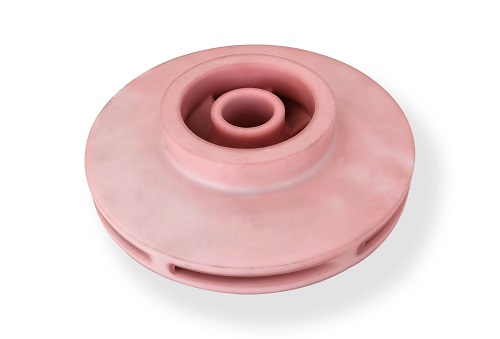
IntroductionYou need strong, functional nylon parts. HP’s Multi Jet Fusion (MJF) 3D printing is a top choice. It makes durable parts with great detail and no supports. But to get reliable results, you must design for it. A bad design leads to warping, trapped powder, and broken parts. This guide gives you the key design rules. You will learn how to set wall thickness, manage powder, and avoid common errors.
Key takeaways
- MJF is a powder bed fusion process. It uses nylon powder (like PA12 or PA11). A print head sprays fusing agent where the part should be.
- MJF commonly uses PA12 (Nylon 12) and PA11 (Nylon 11). Their differences affect design.
- Designing for MJF 3D printing is about respecting the process. Embrace its strengths: complex geometry and isotropic strength.
What Is Special About MJF?
MJF is a powder bed fusion process. It uses nylon powder (like PA12 or PA11). A print head sprays fusing agent where the part should be. Then an infrared lamp passes over, fusing those areas. The loose powder around the part acts as natural support.
Key MJF Traits for Designers
- Isotropic Strength: Parts are equally strong in all directions, unlike FDM.
- No Support Structures: You can design complex overhangs and internal channels.
- Powder is Everywhere: Unfused powder fills hollow areas. You must plan for its removal.
- Thermal Stress: The heating and cooling can cause warping if parts are not designed well.
What Are the Core Design Rules?
Follow these nine strategies to ensure success.
How Thick Should Walls Be?
Wall thickness balances strength and cooling. Too thin walls are brittle. Too thick walls trap heat and warp.
- Minimum Wall: 0.8 mm for unsupported walls. 0.6 mm is possible but risky for tall features.
- Ideal Range: 1.2 mm to 2.0 mm. This gives great strength and even cooling.
- Maximum Wall: Avoid solid blocks over 5-6 mm thick. For thick sections, use a lattice or ribbed structure instead. This saves material and reduces warping.
Pro Tip: Keep wall thickness uniform. Sudden changes from 1mm to 4mm create stress points. Use a gradual taper (1:3 slope) to transition between thick and thin areas.
Case Study: A company printed a sensor housing with 0.5mm walls to save weight. Over 30% cracked during shipping. Increasing the walls to 1.2mm eliminated the cracks. The added weight was minimal, but strength increased dramatically.
How Do You Handle Hollow Parts and Powder?
MJF’s biggest quirk is powder removal. You must let the unfused powder out.
- Escape Holes are Mandatory: Any enclosed cavity needs at least two holes. Place them at opposite ends and low points.
- Minimum Hole Size: 4 mm diameter. Smaller holes get clogged. 5 mm is safer.
- Channels and Internal Passages: Make them as wide and straight as possible. Avoid long, twisting paths. If you have an internal channel, add clean-out ports along its length.
Real Example: A fluid manifold had complex internal channels. The first print trapped powder deep inside. The redesign added three 5mm clean-out ports along the channel path. This allowed full powder recovery with compressed air.
How Do You Avoid Warping?
Warping happens when parts cool unevenly. Large, flat areas are the biggest risk.
- Break Up Large Planes: Don’t design a big, solid, flat plate. Add a ribbed structure on the back or use a lattice infill.
- Use Radiused Corners: Sharp 90-degree corners are stress concentrators. Use a fillet radius of at least 1-2 mm on all inside corners. This spreads stress and reduces warp.
- Consider Part Orientation: In the printer, orient large flat surfaces at a slight angle (5-10 degrees). This improves heat distribution.
What About Moving Parts and Assemblies?
You can print hinges, latches, and snap-fits directly. But they need specific design.
- Clearance for Moving Parts: If printing interlocking parts together (like a chain), you need 0.5 mm to 0.7 mm clearance all around. This allows powder to be removed and gives room for movement.
- Living Hinges: MJF PA12 can make thin, flexible hinges. Design the hinge area to be 0.5-0.7 mm thick and 5-8 mm wide. Ensure the bending direction is parallel to the build plate for best layer strength.
- Snap-Fits: Cantilever snaps are common. The snap arm should have a uniform thickness. The engagement should be shallow to reduce stress. A good rule: the deflection distance should not exceed the arm’s thickness.
How Small Can Details Be?
Fine text and small features can get lost.
- Embossed or Engraved Text: Make letters at least 1.0 mm tall and 0.8 mm wide. Use a bold, sans-serif font.
- Small Holes: For accurate holes, design them 0.2 mm smaller than your target size. The fusing process can slightly close holes. You can always drill them out later.
- Pins and Protrusions: Avoid very thin pins (under 1.5 mm diameter) that are tall. They can be fragile during powder removal.
What Are the Key Specifications?
Keep this table of hard limits and best practices handy.
| Design Feature | Minimum / Recommended | Why It Matters |
|---|---|---|
| Wall Thickness | 0.8 mm (min), 1.2 mm (ideal) | Prevents brittleness and warping. |
| Escape Hole Diameter | 4 mm (min), 5 mm (better) | Allows powder to flow out freely. |
| Clearance (Moving Parts) | 0.5 mm per side | Prevents parts from fusing together. |
| Smallest Reliable Detail | 0.5 mm | Features smaller than this may not form. |
| Text Height | 1.0 mm (min), 2.0 mm (legible) | Survives post-processing blasting. |
| Corner Fillet Radius | 1.0 mm (min) | Reduces stress and improves strength. |
| Max Unsupported Span | 50 mm (for flat areas) | Longer spans may sag or warp. |
How Do You Design for Different Materials?
MJF commonly uses PA12 (Nylon 12) and PA11 (Nylon 11). Their differences affect design.
- PA12: The standard. It has good strength, stiffness, and chemical resistance. Use it for brackets, housings, functional prototypes.
- PA11: More flexible and has higher impact strength. It is derived from castor oil. Use it for snap-fits, living hinges, parts that need to bend. Because it is more flexible, you can design slightly thinner living hinges with PA11.
Material Choice Tip: If your part has integral snap-fits that will be used repeatedly, choose PA11 for its better fatigue resistance.
What Does a Good Workflow Look Like?
Follow this process from design to print.
- Design with MJF in Mind: From the start, apply the rules above. Model with uniform walls, add fillets, and plan powder escape.
- Hollow Strategically: For large parts, use shells with infill (often automatic in MJF software). Don’t make them solid.
- Run a Design Check: Many online MJF services have automated analysis tools. They flag areas with high warping risk or trapped powder.
- Order a Single Test Print: Before committing to 100 parts, print one. Check for fit, strength, and powder removal. This small cost prevents big mistakes.
- Specify Post-Processing: MJF parts come out dusty and grainy. Standard post-processing is media blasting (tumbling) which gives a uniform matte finish. You can also dye parts black or other colors.
How to write a spec that gets priced correctly
A drawing is a contract. If it leaves a number open, the shop fills that number in with its own default. The default is rarely the one you had in mind. Put these five lines on every RFQ and most of the back-and-forth disappears before it starts.
- File format and units, with the model exported in millimetres
- Process and material grade, not a trade name
- Critical features and the tolerance each one needs
- Surface finish and the faces it applies to
- Quantity for the pilot build and for the year
The point is not paperwork. Each line removes a decision the shop would otherwise make for you. A complete RFQ comes back priced. An incomplete one comes back guessed.
What actually drives the price
Buyers usually push on material because it is the line they can see. In practice the material is rarely the biggest number on a quote. These five lines decide most of it:
- build volume and orientation
- layer height and support structure
- material grade and colour
- post-processing and hand finishing
- quantity per build plate
Ask for the quote split by line. A supplier who cannot break it down is guessing, and you will pay for the guess. The line you can usually renegotiate is the tolerance band, not the raw material.
Problems you will meet, and the fix
Every process has a failure mode it prefers. The same four show up again and again on this kind of work, and none of them are mysteries once you know what to look for.
- Warping on long flat faces where the part lifts off the plate
- Layer lines showing through a cosmetic surface
- Support scars on a mating face nobody flagged
- Dimensional drift on thin walls after cooling
Catch the fault on the first part, not the hundredth. A first-article check costs an hour. A bad batch costs the whole order. Write the check into the purchase order so nobody has to remember it.
What to check on the first article
The first article is the cheapest inspection you will ever buy. Use it properly and the rest of the run becomes boring, which is exactly what you want.
- Every dimension on the drawing, with the measured value written beside it.
- The material certificate, matched to the heat or lot number on the parts.
- The finish against the sample you approved, under the same light.
- Fit against the mating part, assembled rather than measured.
- Packaging, because parts that arrive damaged were never in tolerance.
Check in this order: datums, then mating features, then cosmetic faces. If the datums are wrong, every number after them is noise. Keep the report on file. When a problem shows up in month six, that document is the only thing that tells you what changed.
How to compare two quotes fairly
Two numbers are not comparable unless the scope matches. Line them up before you decide, because a low number with three gaps is not a low number.
Same drawing, same material, same finish, same inspection. Anything else is a different job wearing the same part number. Then look at what each quote leaves out. Freight, packaging, certificates and tooling are the usual gaps.
Ask each supplier to state their assumptions in writing. The one who does is usually the one who has run the process before.
Scaling from one part to a batch
The first part teaches you the process. The hundredth teaches you the process cost.
Watch three things as volume grows: setup amortisation, tool wear, and how much hand work the finish still needs. If the unit price barely moves between ten and a hundred, the cost sits in material or in hand work, not in setup. Ask which, because only one of them is negotiable.
Lead time behaves the same way. A one-off is scheduled around other jobs. A repeat order is scheduled around your forecast. Give the shop a forecast and the lead time gets shorter, not longer.
How to read a supplier's quote
A quote is a short document with a long shadow. Four things in it decide whether the job runs smoothly, and only one of them is the price.
- The scope line. It should name the process, the material and the finish, not just the part.
- The tolerance basis. General tolerance or the drawing, and which standard it follows.
- The exclusions. Tooling, freight, certificates and inspection are the usual omissions.
- The validity date. Material prices move, and an open-ended quote is a promise nobody can keep.
Read the exclusions before you read the total. A quote that leaves out tooling is not cheaper. It is a quote for a different job.
What to send with the first order
The first order sets the pattern for every order after it. Send a complete package once and the shop files it, and the second order takes a fraction of the time.
- A STEP or native model plus a PDF drawing carrying the same revision letter.
- The material callout by standard number, not by trade name.
- The finish and the exact faces it applies to.
- Any test the part must pass: fit, seal, drop, salt spray, dielectric.
- A contact who can answer a question inside one working day.
Then write down what was agreed. An email that confirms the material, the finish and the date is worth more than a longer purchase order that leaves them open.
When this is the wrong choice
A good supplier tells you when the process does not fit. These are the cases where we say so.
- The volume is so low that setup costs more than the parts are worth.
- The tolerance is tighter than the process can hold without a second operation.
- The geometry cannot be made without a tool feature that will not pay back.
- The material you need is not available in the form the process requires.
- The schedule is shorter than the tooling or setup time, and nobody has said so yet.
None of these are refusals. They are reasons to look at a different route, and the earlier that conversation happens the cheaper it is. The most expensive mistake in manufacturing is a process chosen before the question was understood.
What Are Common Pitfalls to Avoid?
Learn from others’ mistakes.
- The Solid Block: Designing a part as a solid rectangle. It will likely warp, cost more, and be heavier than needed. Solution: Design with ribs and shells.
- The Sealed Container: Designing a bottle or box with no way for powder to escape. Solution: Always add at least two adequate-sized holes in the initial design.
- The Tiny Text: Adding a detailed serial number 0.5mm tall. It will vanish in finishing. Solution: Use larger text or put the info on a label.
- The Press Fit that’s Too Tight: Designing a hole for a bearing with zero clearance. Shrinkage can make the hole too small. Solution: Design with 0.1-0.2 mm of clearance or plan to ream the hole after printing.
Designing for MJF 3D printing is about respecting the process. Embrace its strengths: complex geometry and isotropic strength. Manage its quirks: powder removal and thermal stress. The key rules are simple: use walls thicker than 0.8mm, add 5mm powder escape holes, avoid large flat surfaces, and fillet your corners. Start with PA12 for most projects. Use PA11 for flexible features. Always print a single test part first to validate your design. By following this guide, you’ll consistently produce strong, reliable, and functional MJF parts.
How we can help
YiguProto runs 3D printing in house, from a single prototype to a production batch. We quote the process, the material and the finish as separate lines, so you can see where the money goes instead of arguing with one number.
Send a STEP file or a drawing and you get a DFM report in one to two business days. It flags the features that add cost and the features that will not hold tolerance on the process you picked.
Every order ships with an inspection report on the features you call out. If a part misses, we make it again. Ready to price a part? Start with a free quote and DFM review, or read more about our 3D printing. You can also talk to an engineer before you commit to a drawing.
Frequently asked questions
How do I compare two quotes fairly?
Match the scope first: same drawing, same material, same finish, same inspection. Then read the exclusions. Freight, tooling and certificates are the usual gaps, and a low number with three gaps is not a low number.
What should I check before approving the parts?
Datums first, then the features that mate, then the cosmetic faces. Ask for a dimensional report, a material certificate and a finish sample. A part can be inside every tolerance and still not fit, so assemble one before you sign.
How long does a first article take?
Usually a few business days once the drawing is frozen, and longer if tooling is involved. The date we give you is the date we confirm in writing, not the date we hope for.
What files do you need in order to quote?
A STEP file plus a PDF drawing that carries the same revision letter. The model carries the geometry and the drawing carries the intent. When the two disagree, the shop picks one, and it is never the one you meant.
Does the process work for prototypes as well as production?
Yes, and that is usually the point. Running the prototype on the production process removes a whole class of surprises, because the part you test is made the same way as the part you sell.
What material should I specify?
Specify by standard, not by trade name. A trade name can change under you between two orders; a standard number cannot. Then add the one property that actually decides the part, whether that is strength, heat resistance or chemical exposure.
The short version
Good parts reward the buyer who reads the data sheet and the drawing together. Pick the option for the property that matters, not for the price per kilo.
Tighten only what mates. Test a sample before the run. Then let the process do the rest.