
Die Casting
What Is Die Casting Clip and How to Solve This Surface Defect?
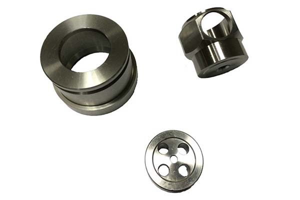
Die casting clip ruins the surface of otherwise good castings. You see it as layers peeling away from the metal, like sheets of paper separating. Touch it and pieces may flake off. For automotive parts or electronic components, this defect means scrap. But what actually causes this layered peeling? Why does it happen in some shots but not others? And how can you stop it from ruining your production runs?
What Exactly Is Die Casting Clip?
Core definition
Die casting clip is a surface defect where metal layers separate instead of bonding together. The part looks like it has a skin that didn’t quite stick to the core. When you examine the surface, you see visible delamination or peeling that follows the shape of the mold cavity.
This is not a scratch or a stain. Those are surface issues. Clip is structural—the layers never properly fused. Under stress, the surface can peel away completely, exposing the metal underneath.
How it differs from other defects
Ordinary surface scratches come from handling damage. They are random and shallow. Die casting clip follows predictable patterns related to how metal flowed in the mold. The peeled areas often have smooth inner surfaces, showing that fusion never happened during solidification.
Porosity leaves holes inside the metal. Clip leaves layers that pull apart. Both weaken parts, but clip is visible immediately while porosity hides until machining.
Why it matters
For decorative parts, clip means rejection at final inspection. No customer accepts peeling surfaces on visible products. For functional parts, clip creates stress concentration points where cracks start. A bracket with clip might look fine on Monday and break on Tuesday.
The cost adds up fast. A 2% clip rate on 100,000 parts means 2,000 scrapped components. At $5 each, that is $10,000 lost. For high-volume production, eliminating clip directly improves profitability.
What Does Die Casting Clip Look Like?
Visual characteristics
Clip appears as thin layers lifting from the surface. You might see a flap of metal that you can lift with a fingernail. The edges of the peeled area are often sharp and defined, matching flow patterns from the mold.
Sometimes clip shows as feathery edges where layers started separating but haven’t fully peeled. In severe cases, you see multiple layers like an onion skin.
Location patterns
Clip typically appears in specific areas. Near gates where metal first enters the cavity. Around cores and inserts where flow splits and rejoins. On opposite sides of thick sections where cooling rates differ.
If you track clip locations, they often repeat on the same spot of every defective part. That consistency points to a process or tooling cause, not random variation.
What Causes Die Casting Clip?
Mold-related causes
Insufficient mold rigidity lets the tool flex during injection. When the mold moves, metal flow becomes uneven. Layers form at different times and never bond properly. The jitter creates shear planes between early and late-filling metal.
Excessive gaps between sliding parts allow metal to seep in. That thin flash gets trapped between layers, creating a mechanical barrier to bonding. When the part ejects, the layers separate at those embedded flash lines.
Local hot spots in the cavity make metal stick to the mold surface. When ejection pulls the part free, the stuck layer tears away from the base metal. The result looks like peeling but started as adhesion.
| Mold Issue | How It Creates Clip |
|---|---|
| Low rigidity | Mold flex causes uneven flow and layered filling |
| Excessive gaps | Flash gets trapped between layers |
| Hot spots | Metal sticks, then tears during ejection |
Injection process problems
Punch crawling means the injection piston moves in jerks instead of smoothly. Fast then slow then fast again. Each speed change creates a flow front discontinuity. Metal that solidifies during a slow period doesn’t bond with metal that arrives later at higher speed.
Disordered metal flow happens when the sprue system doesn’t fill the cavity in the right sequence. Metal goes where it shouldn’t, creating folds and interfaces where layers meet cold instead of fusing. The black oil trace method shows this clearly—oil marks reveal exactly where flow went wrong.
Injection speed wrong for the alloy causes problems too. Too fast creates turbulence that folds metal over itself. Too slow lets the front freeze before the cavity fills.
Material and management factors
Alloy composition fluctuations change how metal behaves. Too much silicon or copper can increase affinity with the mold, promoting sticking and subsequent tearing. Even small shifts of ±0.1% in key elements matter.
Dirty parting surfaces carry over flash and residue from previous shots. When the mold closes, that debris gets pressed into the new casting. It becomes a physical separation layer that prevents metal-to-metal bonding.
Release agent problems contribute too. Too little and metal sticks. Too much and the agent itself creates a barrier between layers. Inconsistent spraying makes the problem worse.
| Factor Category | Specific Cause | How It Creates Clip |
|---|---|---|
| Mold | Low rigidity, gaps, hot spots | Uneven flow, trapped flash, sticking |
| Injection | Punch crawling, disordered flow | Discontinuous filling, cold interfaces |
| Material | Composition shifts, contamination | Changed behavior, physical barriers |
| Management | Dirty molds, uneven release agent | Carryover contamination, inconsistent coating |
How Do You Diagnose Die Casting Clip?
Visual inspection first
Look at the defect pattern. Does it appear on every part or just some? Same location or random? Consistent patterns point to tooling. Random patterns suggest process variation.
Check the peeled surface. Smooth and shiny means it never bonded—the metal was too cold or oxidized. Rough and torn means it bonded but pulled apart—probably from ejection stress.
Use the black oil trace method
Apply black oil to the mold cavity. Run a test shot. The oil leaves dark marks where metal flowed first. Clean areas filled later. This shows exactly how your filling sequence works.
If clip appears where oil marks show flow fronts meeting, you have a flow synchronization problem. If clip follows the boundary between oiled and clean areas, you have temperature or solidification issues.
Check your data
Review process logs. Does clip correlate with specific mold temperatures? With certain injection speeds? With batches of alloy? Data often reveals causes that visual inspection misses.
What Solutions Actually Work?
Fix the mold first
Increase mold rigidity by tightening all components. Check guide pillars, bolts, and templates. Add reinforcing ribs to high-stress areas if needed. A rigid mold eliminates jitter that causes uneven flow.
Measure and adjust sliding part gaps. For aluminum, keep gaps between 0.05 and 0.1mm. Use feeler gauges to check. If gaps exceed spec, repair or replace worn parts. This stops flash from getting trapped between layers.
Control cavity temperature uniformly. Use CAE simulation to find hot spots. Add point cooling channels to those areas. Adjust spray patterns to cool locally. Uniform temperature means uniform solidification and less sticking.
| Mold Fix | What It Does | Expected Improvement |
|---|---|---|
| Increase rigidity | Eliminates flex-induced flow variation | 30–50% clip reduction |
| Adjust gaps | Prevents trapped flash | 20–40% clip reduction |
| Control temperature | Reduces sticking and tearing | 15–30% clip reduction |
Optimize the injection process
Fix punch crawling by checking wear on the punch and pressure chamber. If the pressure chamber wall is scratched, re-polish it. Adjust lubrication—use high-temperature oil designed for die casting. Smooth movement means uniform injection speed.
Reconstruct the sprue system based on black oil trace results. Move gate locations. Adjust cross-sectional areas. The goal is synchronized cavity filling where metal arrives everywhere at once instead of in stages.
Match injection speed to your specific alloy. Different alloys need different profiles. Start with manufacturer recommendations, then fine-tune based on your part geometry. The right speed prevents both turbulence and premature freezing.
Improve material and management
Monitor alloy composition with spectral analysis before melting. Keep key elements within tight ranges—±0.1% for critical elements like magnesium in aluminum. Consistent chemistry means consistent behavior.
Clean parting surfaces every cycle. Use high-pressure air or non-metallic scrapers. Never use steel tools that scratch the mold. Scratches become nucleation sites for sticking.
Standardize release agent application. Use automatic spray systems for consistency. Control coating thickness—aim for 5–8μm uniform film. Too thin lets metal stick. Too thick creates a barrier between layers.
| Process Fix | What It Does | Expected Improvement |
|---|---|---|
| Fix punch crawling | Smooth, uniform injection | 25–40% clip reduction |
| Optimize sprue | Synchronized filling | 30–50% clip reduction |
| Control composition | Predictable metal behavior | 15–25% clip reduction |
| Clean molds regularly | No carryover contamination | 10–20% clip reduction |
What Does a Real Fix Look Like?
I worked with an automotive parts supplier making transmission brackets. Their clip rate hit 8%—thousands of scrapped parts monthly. The defect always appeared near the same core pin.
We started with black oil traces. The oil showed metal splitting around the core pin and rejoining on the far side. But it rejoined at different times—one flow front arrived 0.2 seconds before the other. That cold interface became the clip line.
The fix combined several approaches. We enlarged the gate on the slow side to speed up filling. We added cooling to the core pin to keep temperature uniform. We adjusted injection speed to smooth the flow.
Clip rate dropped to under 1% within a week. The $40,000 in monthly scrap savings paid for the engineering time many times over.
Another electronics manufacturer had clip on thin-walled housings. Their defect appeared random—sometimes on the left, sometimes on the right. Tracking data showed correlation with release agent spray patterns. When the automatic sprayer clogged partially, coating thickness varied. Thin spots caused sticking. Thick spots created barriers.
Cleaning the spray nozzles daily and adding flow meters to verify coverage eliminated the problem. Clip dropped from 5% to 0.3%. The fix cost almost nothing.
How to write a spec that gets priced correctly
A drawing is a contract. If it leaves a number open, the shop fills that number in with its own default. The default is rarely the one you had in mind. Put these five lines on every RFQ and most of the back-and-forth disappears before it starts.
- 3D model with the parting line marked
- Alloy grade and the standard it meets
- Wall thickness and draft on every face
- Machining allowance on the faces that will be cut
- Pressure tightness or porosity class
The point is not paperwork. Each line removes a decision the shop would otherwise make for you. A complete RFQ comes back priced. An incomplete one comes back guessed.
What actually drives the price
Buyers usually push on material because it is the line they can see. In practice the material is rarely the biggest number on a quote. These five lines decide most of it:
- die steel and cavity count
- part weight and wall section
- draft and slide count
- porosity requirement
- machining allowance
Ask for the quote split by line. A supplier who cannot break it down is guessing, and you will pay for the guess. The line you can usually renegotiate is the tolerance band, not the raw material.
Problems you will meet, and the fix
Every process has a failure mode it prefers. The same four show up again and again on this kind of work, and none of them are mysteries once you know what to look for.
- Cold shuts where two flow fronts meet
- Porosity that shows up only after machining
- Soldering on a hot spot in the die
- Shrinkage voids in a heavy section
Catch the fault on the first part, not the hundredth. A first-article check costs an hour. A bad batch costs the whole order. Write the check into the purchase order so nobody has to remember it.
What to check on the first article
The first article is the cheapest inspection you will ever buy. Use it properly and the rest of the run becomes boring, which is exactly what you want.
- Every dimension on the drawing, with the measured value written beside it.
- The material certificate, matched to the heat or lot number on the parts.
- The finish against the sample you approved, under the same light.
- Fit against the mating part, assembled rather than measured.
- Packaging, because parts that arrive damaged were never in tolerance.
Check in this order: datums, then mating features, then cosmetic faces. If the datums are wrong, every number after them is noise. Keep the report on file. When a problem shows up in month six, that document is the only thing that tells you what changed.
How to compare two quotes fairly
Two numbers are not comparable unless the scope matches. Line them up before you decide, because a low number with three gaps is not a low number.
Same drawing, same material, same finish, same inspection. Anything else is a different job wearing the same part number. Then look at what each quote leaves out. Freight, packaging, certificates and tooling are the usual gaps.
Ask each supplier to state their assumptions in writing. The one who does is usually the one who has run the process before.
How Do You Prevent Clip Long-Term?
Build a defect traceability system
Record every clip occurrence with time, mold number, and process parameters. Look for correlations. Does clip increase when mold temperature exceeds 220°C? When injection speed drops below 4 m/s? Data tells you what to fix.
Train operators to recognize early signs
Operators should know what clip looks like in its earliest stages. Train them to check first shots after startups and after any process change. Early detection means quick correction before hundreds of bad parts accumulate.
Schedule preventive maintenance
Don’t wait for clip to appear before fixing molds. Schedule regular gap checks, polishings, and rigidity inspections. Replace worn components on a schedule, not after failure.
Standardize your process
Write down exactly how you set up each job. Target temperatures, speeds, pressures, and spray times. Follow the same recipe every time. Variation causes defects.
Die casting clip ruins parts and eats profits, but it is entirely preventable. The defect comes from mold issues, injection problems, or material factors—each with clear solutions. Fix rigid molds, control gaps, and manage temperature. Stop punch crawling and optimize flow sequences. Maintain consistent alloy chemistry and clean molds. A systematic approach combining diagnosis, targeted fixes, and ongoing monitoring typically cuts clip rates from several percent to under 0.5%. For high-volume production, that improvement saves tens of thousands annually while delivering better parts to your customers.
Our solution for Die Casting Clip
YiguProto runs die casting in house, from a single prototype to a production batch. We quote the process, the material and the finish as separate lines, so you can see where the money goes instead of arguing with one number.
Send a STEP file or a drawing and you get a DFM report in one to two business days. It flags the features that add cost and the features that will not hold tolerance on the process you picked.
Every order ships with an inspection report on the features you call out. If a part misses, we make it again. Ready to price a part? Start with a free quote and DFM review, or read more about our die casting. You can also talk to an engineer before you commit to a drawing.
FAQ about Die Casting Clip
What should I check before approving the parts?
Datums first, then the features that mate, then the cosmetic faces. Ask for a dimensional report, a material certificate and a finish sample. A part can be inside every tolerance and still not fit, so assemble one before you sign.
What is the lead time for Die Casting Clip?
Expect 20 to 30 business days including die build. Tooling, material stock and the finishing queue all move that number, so we confirm the date in writing before the run starts rather than after.
What tolerance can you hold on Die Casting Clip?
The working default is ±0.1 mm on cast features, ±0.05 mm after machining. Tighter than that the process changes and so does the price, because every step tighter adds inspection time. Call out only the faces that mate with something else and leave the rest on the general tolerance.
What is Die Casting Clip used for?
Die Casting Clip turns up wherever the part has to do a real job at a predictable cost: brackets, housings, fixtures, covers and the fittings that hold them together. The honest test is whether the properties match the load and the environment, not whether the material is fashionable.
What material should I specify?
Specify by standard, not by trade name. A trade name can change under you between two orders; a standard number cannot. Then add the one property that actually decides the part, whether that is strength, heat resistance or chemical exposure.
What files do you need in order to quote?
A STEP file plus a PDF drawing that carries the same revision letter. The model carries the geometry and the drawing carries the intent. When the two disagree, the shop picks one, and it is never the one you meant.
The short version
Die Casting Clip rewards the buyer who reads the data sheet and the drawing together. Pick the option for the property that matters, not for the price per kilo.
Tighten only what mates. Test a sample before the run. Then let the process do the rest.