
Die Casting
What Are Die-Casting Ejector Pins and How to Optimize Their Performance?
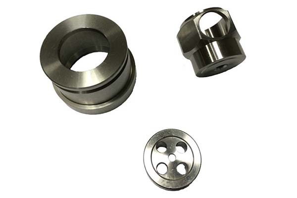
If you work with die casting, you know that every part of the process matters. But some components get less attention than they deserve. Ejector pins are exactly that—small, simple-looking parts that play a huge role. When they work well, castings release smoothly and production runs without interruption. When they fail, you get bent parts, damaged molds, and costly downtime.
Key takeaways
- Ejector pins are cylindrical components installed in the moving half of a die casting mold.
- The challenge: An A356 aluminum motor housing, 300mm deep, with 16 heat dissipation fins (2mm thick, 15mm tall).
- Die-casting ejector pins are small but essential. They ensure castings release cleanly, protect expensive molds, and keep production running.
What Are Die-Casting Ejector Pins?
Ejector pins are cylindrical components installed in the moving half of a die casting mold. After the molten metal solidifies, these pins push the casting off the mold, allowing it to be removed.
The Basic Function
Think of them as the “push” at the end of every cycle. Without them, castings would stay stuck in the mold. Production would stop. Every cycle depends on these small parts working reliably.
Why Are They Critical?
Controlled release: They apply just enough force to separate the casting without damaging it. A thin-walled phone frame needs 50–80N of force—too little causes sticking, too much bends the part.
Mold protection: By releasing castings gently, they prevent scratching or chipping the mold cavity. A damaged cavity costs $10,000+ to repair. Good ejector pins extend mold life by 20–30%.
Casting integrity: Multiple pins distribute force evenly. Properly spaced pins cut deformation rates from 8% to under 1%.
Production speed: They integrate with the mold cycle (60–120 seconds per cycle). Smart pins with sensors can adjust force in real time, cutting cycle time by 5–10%.
What Types of Ejector Pins Exist?
Different castings need different pin designs.
| Pin Type | Key Features | Best Applications |
|---|---|---|
| Standard cylindrical | Diameter 3–20mm; flat tip; length/diameter ratio ≤8:1 | Simple castings: zinc toys, small aluminum brackets |
| Segmented | 1–3 telescoping sections; 20–50mm stroke | Deep cavities: EV motor housings (300mm deep), magnesium camera shells |
| Flat section | Wide tip (10–30mm); polished surface (Ra 0.8μm) | Large flat parts: laptop palm rests, automotive door panels |
| Air-blowing | Hollow body with 0.5–1mm air channel; 0.5–0.8MPa air pressure | Thin walls: aluminum heat sinks (0.8mm), foam aluminum |
| Inductive smart | Built-in force and temperature sensors; wireless data | High-value: aerospace brackets, medical components |
How Do You Design Ejector Pins for Reliability?
Calculating the Right Diameter
The formula is straightforward but critical:
D = √[(F × K) / σ_allowed]
Where:
- F = Required ejector force (N) = A × μ × P
- A = casting projection area (mm²)
- μ = friction coefficient (0.15–0.2 for aluminum)
- P = mold clamping pressure (MPa)
- K = Safety factor (1.5–2.0)
- σ_allowed = Material allowable stress (MPa)
Example: An aluminum casting with A=10,000mm², μ=0.18, P=50MPa:
- F = 10,000 × 0.18 × 50 = 90,000N
- D = √[(90,000 × 1.8) / 800] ≈ 14.3mm → Use 15mm diameter
Length-to-Diameter Ratio
Keep this ratio ≤8:1 to prevent bending. For a 100mm long pin, minimum diameter is 12.5mm.
If you must use a slimmer pin (ratio >8:1), add guide bushings every 50mm of length. The bushing inner diameter should be pin diameter + 0.02mm.
Layout Principles
Margin requirement: Keep pins at least 3mm away from the mold cavity. This prevents cavity chipping.
Force uniformity: The force difference between any two pins should be under 10%. Use simulation software to optimize spacing—put pins closer to thick areas (higher sticking force) and farther from thin walls.
Angle design: Tilt pins 5°–15° relative to the parting surface. This:
- Improves exhaust (air escapes during ejection)
- Reduces sliding friction (extends pin life by 15%)
Material Selection
Match pin material to your casting alloy.
| Casting Alloy | Recommended Pin Material | Surface Treatment | Life (cycles) |
|---|---|---|---|
| Aluminum (ADC12, A380) | H13 hot work mold steel | Quench + nitride (50–70μm) | 150,000–200,000 |
| Magnesium (AZ91D) | QRO-90 SUPREME | CVD TiAlN coating (3–5μm) | 80,000–120,000 |
| High-silicon aluminum | YG8 tungsten carbide | Diamond polish (Ra ≤0.05μm) | 500,000+ |
| Zinc (ZAMAK 5) | SKD61 mold steel | Chrome plating (10–15μm) | 300,000–400,000 |
Key insight: For high-silicon aluminum (growing in EV applications), tungsten carbide costs more but lasts 500,000+ cycles—3× longer than H13. The higher upfront cost pays off in reduced downtime.
What Causes Ejector Pin Failure and How Do You Fix It?
Tip Smoothing and Wear
Cause: Sliding friction heats the pin tip to 200–300°C (for aluminum). Repeated heating softens the material.
Solutions:
- Upgrade to powder metallurgy high-speed steel (ASP-60)—2× harder than H13
- Apply laser cladding (tungsten carbide layer, 0.5–1mm thick) to the tip
- Increase lubrication frequency—from weekly to daily with PAG synthetic oil
Pin Fracture
Cause: Fatigue cracks at the fixed seat transition (sharp corners); excessive force (over 150% of design); bent pins.
Solutions:
- Increase fillet radius from R1 to R3 or larger—cuts stress concentration by 50%
- Install force sensors—trigger alarm if force exceeds 120% of setpoint
- Replace bent pins immediately; add guide bushings to prevent future bending
Pin Sticking and Jamming
Cause: Aluminum chips accumulate in the pin-mold gap (0.02–0.05mm); mold too hot (metal adheres); insufficient lubrication.
Solutions:
- Add self-cleaning spiral groove (1mm deep, 10mm pitch) to expel chips
- Lower mold temperature 20–30°C (e.g., 250°C → 220°C for aluminum)
- Use dry lubricant (molybdenum disulfide spray) in addition to oil—cuts adhesion by 70%
Uneven Tip Wear
Cause: Poor guide accuracy (pin tilts); mold cavity misalignment; dirty bushings.
Solutions:
- Replace standard bushings with linear bearing guide columns (±0.01mm accuracy)
- Realign mold cavity with laser alignment tool (misalignment under 0.02mm)
- Clean guide bushings daily with compressed air; replace every 50,000 cycles
Real-World Example: EV Motor Housing
The challenge: An A356 aluminum motor housing, 300mm deep, with 16 heat dissipation fins (2mm thick, 15mm tall).
Problems:
- Deep cavity created high sticking force—standard pins couldn’t release it
- Thin fins bent during ejection
- Demolding took 5+ seconds (slowing production)
The solution: Three-stage linkage system
- 8 main pins (φ8mm, H13, nitrided) around outer edge—provide initial 80% of ejection force
- 6 ultra-slender fin pins (φ3mm, tungsten carbide) between fins—apply targeted force without bending
- 4 air-blowing pins (φ5mm) release compressed air (0.6MPa) 0.5s after main ejection—break vacuum between fins and mold
The results:
- Demolding time: 5s → 2.3s (54% faster)
- Yield rate: 92% → 99.6% (no more fin bending)
- Pin life: Tungsten carbide pins lasted 300,000 cycles—2× longer than H13
How Do You Maintain Ejector Pins?
Daily (Every Shift)
Clean: Wipe pins with lint-free cloth. For spiral grooves, use a 0.5mm brush.
Lubricate: Apply 2–3 drops of PAG synthetic oil to each guide bushing. Don’t overdo it—excess oil can mix with molten metal and cause defects.
Inspect: Look for tip wear, bending, or corrosion. Mark damaged pins for replacement.
Monthly
Measure: Use digital caliper to check tip diameter. Replace if wear exceeds 0.1mm (e.g., 10mm pin worn to 9.9mm).
Test force: Use a dynamometer to verify ejection force. Should stay within ±10% of design.
Check bushings: Replace if inner diameter exceeds pin diameter by >0.05mm (causes deflection).
Spare Parts Strategy
Stock ratio: Keep 1:2 spare ratio for critical pins (20 spares for 10 active pins).
Lead time: Ensure custom pins (e.g., φ3mm tungsten carbide) have ≤7 day lead time from supplier.
Labeling: Mark spares with material, diameter, length (e.g., “H13, φ8mm, 100mm”) for quick identification.
How to write a spec that gets priced correctly
A drawing is a contract. If it leaves a number open, the shop fills that number in with its own default. The default is rarely the one you had in mind. Put these five lines on every RFQ and most of the back-and-forth disappears before it starts.
- 3D model with the parting line marked
- Alloy grade and the standard it meets
- Wall thickness and draft on every face
- Machining allowance on the faces that will be cut
- Pressure tightness or porosity class
The point is not paperwork. Each line removes a decision the shop would otherwise make for you. A complete RFQ comes back priced. An incomplete one comes back guessed.
What actually drives the price
Buyers usually push on material because it is the line they can see. In practice the material is rarely the biggest number on a quote. These five lines decide most of it:
- die steel and cavity count
- part weight and wall section
- draft and slide count
- porosity requirement
- machining allowance
Ask for the quote split by line. A supplier who cannot break it down is guessing, and you will pay for the guess. The line you can usually renegotiate is the tolerance band, not the raw material.
Problems you will meet, and the fix
Every process has a failure mode it prefers. The same four show up again and again on this kind of work, and none of them are mysteries once you know what to look for.
- Cold shuts where two flow fronts meet
- Porosity that shows up only after machining
- Soldering on a hot spot in the die
- Shrinkage voids in a heavy section
Catch the fault on the first part, not the hundredth. A first-article check costs an hour. A bad batch costs the whole order. Write the check into the purchase order so nobody has to remember it.
What to check on the first article
The first article is the cheapest inspection you will ever buy. Use it properly and the rest of the run becomes boring, which is exactly what you want.
- Every dimension on the drawing, with the measured value written beside it.
- The material certificate, matched to the heat or lot number on the parts.
- The finish against the sample you approved, under the same light.
- Fit against the mating part, assembled rather than measured.
- Packaging, because parts that arrive damaged were never in tolerance.
Check in this order: datums, then mating features, then cosmetic faces. If the datums are wrong, every number after them is noise. Keep the report on file. When a problem shows up in month six, that document is the only thing that tells you what changed.
How to compare two quotes fairly
Two numbers are not comparable unless the scope matches. Line them up before you decide, because a low number with three gaps is not a low number.
Same drawing, same material, same finish, same inspection. Anything else is a different job wearing the same part number. Then look at what each quote leaves out. Freight, packaging, certificates and tooling are the usual gaps.
Ask each supplier to state their assumptions in writing. The one who does is usually the one who has run the process before.
Scaling from one part to a batch
The first part teaches you the process. The hundredth teaches you the process cost.
Watch three things as volume grows: setup amortisation, tool wear, and how much hand work the finish still needs. If the unit price barely moves between ten and a hundred, the cost sits in material or in hand work, not in setup. Ask which, because only one of them is negotiable.
Lead time behaves the same way. A one-off is scheduled around other jobs. A repeat order is scheduled around your forecast. Give the shop a forecast and the lead time gets shorter, not longer.
How to read a supplier's quote
A quote is a short document with a long shadow. Four things in it decide whether the job runs smoothly, and only one of them is the price.
- The scope line. It should name the process, the material and the finish, not just the part.
- The tolerance basis. General tolerance or the drawing, and which standard it follows.
- The exclusions. Tooling, freight, certificates and inspection are the usual omissions.
- The validity date. Material prices move, and an open-ended quote is a promise nobody can keep.
Read the exclusions before you read the total. A quote that leaves out tooling is not cheaper. It is a quote for a different job.
FAQ About Die-Casting Ejector Pins
How many ejector pins do I need for my casting?
Calculate based on total ejection force divided by the safe load per pin. Start with 80% of the mold surface covered by pins (spaced 20–50mm apart). Use simulation to verify uniform force distribution. More pins with lower force each is better than fewer pins with high force.
Can I reuse ejector pins from old molds?
Not recommended. Pins wear to match their original mold. Using them in a new mold risks misalignment, uneven force, and casting defects. Always use new pins matched to the new mold’s dimensions.
What is the ideal gap between pin and mold?
0.02–0.05mm for aluminum. Too tight: pin binds. Too loose: metal flashes into the gap, causing sticking. For magnesium, use the tighter end of the range (0.02mm) to prevent oxide buildup.
How do I know when to replace ejector pins?
Replace when:
- Tip wear exceeds 0.1mm
- Visible bending or cracking
- Casting shows ejector marks (small dents at pin locations)
- Ejection force deviates more than 10% from baseline
- After 150,000 cycles for H13; 300,000+ for tungsten carbide
Can ejector pins be repaired instead of replaced?
Minor tip wear can be ground flat (remove 0.1–0.2mm) if length allows. But this changes the pin’s effective stroke—adjust the ejector plate accordingly. For cracks or bending, always replace—repairing risks catastrophic failure.
Die-casting ejector pins are small but essential. They ensure castings release cleanly, protect expensive molds, and keep production running. Getting them right requires attention to:
Design: Calculate diameter based on force, keep length/diameter ratio under 8:1, lay out pins for uniform force, and match material to casting alloy.
Selection: Choose from cylindrical, segmented, flat, air-blowing, or smart pins based on part geometry. Match material to the casting—tungsten carbide for high-silicon aluminum, H13 for standard aluminum, QRO-90 for magnesium.
Maintenance: Clean and lubricate daily. Check wear monthly. Replace at first sign of damage. Keep spares ready.
Problem-solving: Tip wear? Upgrade material or coating. Pin fracture? Add radius and monitor force. Sticking? Add spiral grooves or adjust temperature.
The numbers tell the story: properly designed and maintained ejector pins cut deformation rates from 8% to under 1%, extend mold life by 20–30%, and reduce cycle time by 5–10%. In high-volume production, that is real money.
Treat ejector pins as the critical components they are—not as afterthoughts. Your castings, your molds, and your production schedule will thank you.
Our solution for Die-Casting Ejector Pins
YiguProto runs die casting in house, from a single prototype to a production batch. We quote the process, the material and the finish as separate lines, so you can see where the money goes instead of arguing with one number.
Send a STEP file or a drawing and you get a DFM report in one to two business days. It flags the features that add cost and the features that will not hold tolerance on the process you picked.
Every order ships with an inspection report on the features you call out. If a part misses, we make it again. Ready to price a part? Start with a free quote and DFM review, or read more about our die casting. You can also talk to an engineer before you commit to a drawing.
FAQ about Die-Casting Ejector Pins
What files do you need in order to quote?
A STEP file plus a PDF drawing that carries the same revision letter. The model carries the geometry and the drawing carries the intent. When the two disagree, the shop picks one, and it is never the one you meant.
What is the lead time for Die-Casting Ejector Pins?
Expect 20 to 30 business days including die build. Tooling, material stock and the finishing queue all move that number, so we confirm the date in writing before the run starts rather than after.
What material should I specify?
Specify by standard, not by trade name. A trade name can change under you between two orders; a standard number cannot. Then add the one property that actually decides the part, whether that is strength, heat resistance or chemical exposure.
What tolerance can you hold on Die-Casting Ejector Pins?
The working default is ±0.1 mm on cast features, ±0.05 mm after machining. Tighter than that the process changes and so does the price, because every step tighter adds inspection time. Call out only the faces that mate with something else and leave the rest on the general tolerance.
Is there a minimum order quantity?
No hard minimum. One part is fine. What changes with volume is which costs dominate, so a single unit is priced mostly on setup and a thousand units are priced mostly on cycle time and material.
What happens if a part is out of specification?
We measure it against the same drawing you approved and, if it misses, we make it again. What matters is that the report exists, because a disagreement without data is just an opinion.
The short version
Die-Casting Ejector Pins rewards the buyer who reads the data sheet and the drawing together. Pick the option for the property that matters, not for the price per kilo.
Tighten only what mates. Test a sample before the run. Then let the process do the rest.