
Die Casting
What Are Die Casting Exhaust Grooves and How to Design Them for Optimal Performance?
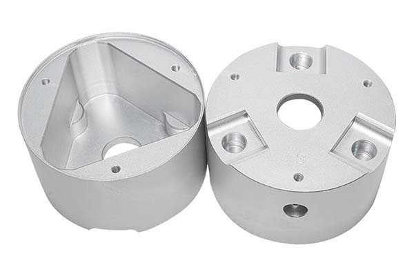
If you have ever struggled with porosity, cold shuts, or incomplete filling in your die cast parts, the problem might be right in front of you—or rather, missing. Exhaust grooves are the small channels in your mold that let trapped air escape. When they work well, you barely notice them. When they fail, defects appear everywhere.
Key takeaways
- Exhaust grooves are the “respiratory system” of your mold. They do more than just let air out.
- The challenge: An aluminum battery frame (A356 alloy) had porosity defects in 12% of production. X-ray showed gas trapped at rib intersections.
- Die casting exhaust grooves are small features with huge impact. When designed correctly, they:
What Do Exhaust Grooves Actually Do?
Exhaust grooves are the “respiratory system” of your mold. They do more than just let air out.
Primary Function: Removing Harmful Gases
Three types of gas must be expelled during filling:
Cavity air: The air already in the mold makes up 60–70% of total gas volume. Without exhaust, this air gets trapped, forming porosity bubbles (0.1–0.5mm) that cut tensile strength by 20–30%. An unvented aluminum motor housing might leak at 5×10⁻⁵ mbar·L/s—failing the 1×10⁻⁶ standard for hydraulic systems.
Volatile gases: Paint and lubricant on the mold vaporize at casting temperatures (200–300°C). These gases cause scorch marks (dark rough patches) and carbon inclusions. Good exhaust cuts scorch marks from 15% to under 2%.
Reaction gases: Molten metal reacts with residual oxygen, forming oxide films. Exhaust removes oxygen before reaction, reducing oxide inclusions by 40–60%.
Secondary Function: Improving Flow
Well-designed exhaust grooves also help metal fill the cavity:
Reducing turbulence: By giving gas an escape path, exhaust prevents “air coiling”—where metal wraps around trapped air, creating vortices that cause cold shuts. For thin walls under 2mm, this cuts underfilling by 70%.
Guiding flow: Strategic exhaust placement (at flow endpoints) encourages even filling. An aluminum laptop palm rest with corner exhaust achieved 98% filling uniformity vs. 82% without.
Cooling balance: Exhaust grooves act as heat sinks in hot spots (thick intersections), preventing overheating that causes shrinkage. This reduces dimensional deviation by 0.1–0.2mm.
What Types of Exhaust Grooves Exist?
Different designs suit different situations.
| Type | Design Features | Optimal Dimensions | Best Applications |
|---|---|---|---|
| Parting surface grooves | Straight or horn-shaped channels on mold parting surface; connect to final filling area | Depth: Al 0.05–0.1mm, Zn 0.03–0.08mm, Mg 0.06–0.12mm; Width: 3–10mm; Length: 10–50mm | Large/medium castings: engine blocks, door handles, battery frames |
| Pushrod gap grooves | Use 0.03–0.05mm gaps between pushrods and mold holes; no extra machining | Pushrod diameter 5–15mm; Gap 0.03–0.05mm | Parts with ejection systems: valve cores, gearbox brackets |
| Insert gap grooves | Gaps between removable inserts (slides, cores); self-cleaning | Gap: Al/Mg 0.04–0.06mm, Zn 0.02–0.04mm; Insert length 50–200mm | Complex parts: turbine casings, camera shells with internal threads |
| Exhaust plug grooves | Embedded porous plugs (sintered steel, ceramic) in high-gas areas; replaceable | Plug diameter 8–20mm; Porosity 20–30%; Gas permeability 10–15 L/min at 0.1MPa | High-precision: medical devices, aerospace brackets |
How Do You Design Exhaust Grooves Correctly?
Location Rules
Place exhaust grooves where gas accumulates:
Final filling areas: The last places metal reaches—opposite the gate, ends of runners.
Deep cavities: Any area deeper than 50mm traps air. Exhaust here is mandatory.
Around cores: Water channel cores, slider pins—any feature surrounded by metal.
Thick-to-thin transitions: Where wall thickness changes, gas can get trapped.
Size Rules
Match dimensions to your alloy:
| Alloy | Depth | Width | Why |
|---|---|---|---|
| Aluminum | 0.05–0.1mm | 3–8mm | Moderate fluidity; balance exhaust vs. flash |
| Zinc | 0.03–0.08mm | 3–5mm | High fluidity; shallow to prevent leakage |
| Magnesium | 0.06–0.12mm | 5–15mm | Low fluidity; deeper to speed exhaust |
Never use one-size-fits-all dimensions. What works for aluminum will cause flash in zinc and porosity in magnesium.
Shape Rules
Horn-shaped grooves: Width increases from cavity to mold edge. This expands gas volume gradually, avoiding sonic flow that traps gas.
No sharp bends: Avoid 90° angles. Use 15–30° angles for smooth flow.
Step-shaped for zinc: For high-fluidity zinc, use grooves that get shallower toward the edge—prevents metal leakage.
Pairing with Overflow Grooves
80% of effective exhaust systems combine overflow and exhaust grooves. The overflow traps cold, oxidized metal that would block exhaust. The exhaust removes gas. For an aluminum EV battery frame, this pairing cut porosity from 8% to 1.2%.
How Do Exhaust Grooves Work with Other Systems?
Coordination with Gating
The gating system determines flow direction—exhaust must align with it.
Gate location: Place exhaust 180° opposite the main gate (farthest point in flow path).
Runner size matching:
- If runner is too large (flow under 1 m/s), gas evacuation slows—increase exhaust width 20–30%
- If runner is too small (flow over 5 m/s), use horn-shaped grooves to avoid gas compression
Coordination with Cooling
Cooling channels must not interfere with exhaust.
Keep distance: Place cooling channels at least 10mm away from exhaust grooves. Closer than 5mm creates a “cold barrier” that traps gas. This mistake caused 25% underfilling in a zinc toy part line.
Use exhaust as cooling: In hot spots, exhaust grooves act as heat sinks. A 5mm-wide, 0.1mm-deep groove can reduce local temperature by 15–20°C.
Simulate: Use software like MAGMA to map temperature distribution. Ensure exhaust zones stay above 200°C (for aluminum)—cold grooves under 150°C cause gas condensation and internal defects.
What Problems Occur and How Do You Fix Them?
Exhaust Groove Clogging
Causes:
- Molten metal residue buildup
- Oxide scales from mold wear
- Infrequent cleaning (monthly instead of weekly)
Solutions:
- Clean daily with 0.1mm steel wire brush (avoids scratching)
- Add self-cleaning slope (5–10° angle) so residue slides out during mold opening
- For zinc, use water-based mold cleaner (pH 7–8) to dissolve residue without damaging mold
Metal Leakage (Flash)
Causes:
- Groove too deep (e.g., 0.15mm for zinc)
- Mold parting surface worn (gap over 0.05mm)
- Injection speed too high (over 5 m/s)
Solutions:
- Reduce depth 30–50% (e.g., 0.1mm → 0.07mm for zinc)
- Resurface parting surface to gap under 0.03mm
- Lower injection speed 1–2 m/s
Incomplete Gas Evacuation
Causes:
- Grooves placed outside gas accumulation zones
- Groove too short (doesn’t reach mold edge)
- Vacuum system leak (over 5%)
Solutions:
- Use filling simulation (AnyCasting) to reposition grooves
- Extend grooves 5–10mm beyond mold edge
- Inspect vacuum hoses; replace seals every 3 months
Uneven Exhaust Across Cavity
Causes:
- Inconsistent groove depth (variation over 0.02mm)
- Multiple cavities with unequal exhaust resistance
- Mold deformation (misaligns grooves)
Solutions:
- Calibrate depth with digital gauge (tolerance ±0.01mm)
- Adjust width per cavity—wider for higher-resistance cavities
- Replace worn mold plates (deformation over 0.1mm)
Real-World Example: EV Battery Frame
The challenge: An aluminum battery frame (A356 alloy) had porosity defects in 12% of production. X-ray showed gas trapped at rib intersections.
The fix:
Simulation: MAGMA analysis identified gas accumulation zones at four locations where ribs met.
Redesign:
- Added horn-shaped parting surface grooves at each zone (0.08mm depth, 8mm width)
- Paired each with overflow grooves (1.2× cavity volume)
- Extended grooves 8mm beyond cavity edge
Process adjustment:
- Reduced injection speed from 4.5 m/s to 3.8 m/s
- Increased mold temperature from 200°C to 220°C at exhaust zones
The results:
- Porosity: 12% → 1.8%
- Scrap cost savings: $200,000/year
- No additional cycle time
How to write a spec that gets priced correctly
A drawing is a contract. If it leaves a number open, the shop fills that number in with its own default. The default is rarely the one you had in mind. Put these five lines on every RFQ and most of the back-and-forth disappears before it starts.
- 3D model with the parting line marked
- Alloy grade and the standard it meets
- Wall thickness and draft on every face
- Machining allowance on the faces that will be cut
- Pressure tightness or porosity class
The point is not paperwork. Each line removes a decision the shop would otherwise make for you. A complete RFQ comes back priced. An incomplete one comes back guessed.
What actually drives the price
Buyers usually push on material because it is the line they can see. In practice the material is rarely the biggest number on a quote. These five lines decide most of it:
- die steel and cavity count
- part weight and wall section
- draft and slide count
- porosity requirement
- machining allowance
Ask for the quote split by line. A supplier who cannot break it down is guessing, and you will pay for the guess. The line you can usually renegotiate is the tolerance band, not the raw material.
Problems you will meet, and the fix
Every process has a failure mode it prefers. The same four show up again and again on this kind of work, and none of them are mysteries once you know what to look for.
- Cold shuts where two flow fronts meet
- Porosity that shows up only after machining
- Soldering on a hot spot in the die
- Shrinkage voids in a heavy section
Catch the fault on the first part, not the hundredth. A first-article check costs an hour. A bad batch costs the whole order. Write the check into the purchase order so nobody has to remember it.
What to check on the first article
The first article is the cheapest inspection you will ever buy. Use it properly and the rest of the run becomes boring, which is exactly what you want.
- Every dimension on the drawing, with the measured value written beside it.
- The material certificate, matched to the heat or lot number on the parts.
- The finish against the sample you approved, under the same light.
- Fit against the mating part, assembled rather than measured.
- Packaging, because parts that arrive damaged were never in tolerance.
Check in this order: datums, then mating features, then cosmetic faces. If the datums are wrong, every number after them is noise. Keep the report on file. When a problem shows up in month six, that document is the only thing that tells you what changed.
How to compare two quotes fairly
Two numbers are not comparable unless the scope matches. Line them up before you decide, because a low number with three gaps is not a low number.
Same drawing, same material, same finish, same inspection. Anything else is a different job wearing the same part number. Then look at what each quote leaves out. Freight, packaging, certificates and tooling are the usual gaps.
Ask each supplier to state their assumptions in writing. The one who does is usually the one who has run the process before.
Scaling from one part to a batch
The first part teaches you the process. The hundredth teaches you the process cost.
Watch three things as volume grows: setup amortisation, tool wear, and how much hand work the finish still needs. If the unit price barely moves between ten and a hundred, the cost sits in material or in hand work, not in setup. Ask which, because only one of them is negotiable.
Lead time behaves the same way. A one-off is scheduled around other jobs. A repeat order is scheduled around your forecast. Give the shop a forecast and the lead time gets shorter, not longer.
How to read a supplier's quote
A quote is a short document with a long shadow. Four things in it decide whether the job runs smoothly, and only one of them is the price.
- The scope line. It should name the process, the material and the finish, not just the part.
- The tolerance basis. General tolerance or the drawing, and which standard it follows.
- The exclusions. Tooling, freight, certificates and inspection are the usual omissions.
- The validity date. Material prices move, and an open-ended quote is a promise nobody can keep.
Read the exclusions before you read the total. A quote that leaves out tooling is not cheaper. It is a quote for a different job.
FAQ About Die Casting Exhaust Grooves
Can I use the same exhaust groove dimensions for aluminum and zinc?
No—disaster waiting to happen. Zinc’s high fluidity needs shallow grooves (0.03–0.08mm) to prevent leakage. Using aluminum-sized grooves (0.1mm) for zinc causes 30% more flash, increasing trimming costs 25%.
How do I know if my exhaust system is effective?
Three metrics:
- Porosity rate: Should be under 2% (X-ray inspection) for structural parts
- Filling uniformity: Over 95% of cavity filled without undercuts (visual inspection of trial parts)
- Surface defects: Scorch marks, cold shuts, oxide inclusions under 3% total
If any metric fails, use filling simulation to identify weak points and adjust.
What’s the difference between exhaust grooves and exhaust plugs?
Exhaust grooves: Machined channels, low cost, easy to maintain. Best for large, simple castings (aluminum brackets).
Exhaust plugs: Porous inserts, higher cost, replaceable. Offer precise gas control. Best for complex parts with internal features (magnesium camera shells) or high-precision applications (medical devices).
For multi-cavity molds, use both: grooves for main gas zones, plugs for hard-to-reach areas.
How often should I clean exhaust grooves?
Daily: Quick brush cleaning to remove light residue.
Weekly: Thorough cleaning with appropriate tools (steel brush for aluminum, water-based cleaner for zinc).
Monthly: Depth calibration with digital gauge; resurface if variation exceeds 0.02mm.
What causes exhaust grooves to wear unevenly?
Three main culprits:
- Uneven mold temperature: Hot spots expand more, changing groove dimensions
- Misaligned mold halves: Causes preferential wear on one side
- Abrasive alloys: High-silicon aluminum wears grooves faster
Solutions: Balance mold temperature, check alignment quarterly, and for high-silicon alloys, use exhaust plugs instead of machined grooves.
Die casting exhaust grooves are small features with huge impact. When designed correctly, they:
- Remove cavity air, volatiles, and reaction gases
- Cut porosity by 80–90%
- Improve filling uniformity to over 95%
- Reduce surface defects from 15% to under 2%
Success requires attention to:
- Location: Final filling areas, deep cavities, around cores
- Size: Match to alloy (aluminum 0.05–0.1mm, zinc 0.03–0.08mm, magnesium 0.06–0.12mm)
- Shape: Horn-shaped for smooth flow, step-shaped for zinc
- Coordination: With gating (180° from gate) and cooling (≥10mm distance)
- Maintenance: Daily cleaning, weekly calibration
The evidence is clear: one manufacturer cut porosity from 12% to 1.8% and saved $200,000/year by redesigning exhaust grooves. Another reduced scorch marks from 15% to under 2%. These are not small improvements—they are game-changers for quality and cost.
Treat exhaust grooves as the critical design element they are. Your parts will be denser, your surfaces smoother, and your scrap rate lower.
Our solution for Die Casting Exhaust Grooves
YiguProto runs die casting in house, from a single prototype to a production batch. We quote the process, the material and the finish as separate lines, so you can see where the money goes instead of arguing with one number.
Send a STEP file or a drawing and you get a DFM report in one to two business days. It flags the features that add cost and the features that will not hold tolerance on the process you picked.
Every order ships with an inspection report on the features you call out. If a part misses, we make it again. Ready to price a part? Start with a free quote and DFM review, or read more about our die casting. You can also talk to an engineer before you commit to a drawing.
FAQ about Die Casting Exhaust Grooves
What files do you need in order to quote?
A STEP file plus a PDF drawing that carries the same revision letter. The model carries the geometry and the drawing carries the intent. When the two disagree, the shop picks one, and it is never the one you meant.
What happens if a part is out of specification?
We measure it against the same drawing you approved and, if it misses, we make it again. What matters is that the report exists, because a disagreement without data is just an opinion.
What is Die Casting Exhaust Grooves used for?
Die Casting Exhaust Grooves turns up wherever the part has to do a real job at a predictable cost: brackets, housings, fixtures, covers and the fittings that hold them together. The honest test is whether the properties match the load and the environment, not whether the material is fashionable.
What should I check before approving the parts?
Datums first, then the features that mate, then the cosmetic faces. Ask for a dimensional report, a material certificate and a finish sample. A part can be inside every tolerance and still not fit, so assemble one before you sign.
How much does Die Casting Exhaust Grooves cost?
Price comes from five lines: material, machine or tool time, setup, finishing and inspection. The material itself is usually the smallest of them. Send a drawing and we will split the quote so you can see which line is doing the damage.
What is the lead time for Die Casting Exhaust Grooves?
Expect 20 to 30 business days including die build. Tooling, material stock and the finishing queue all move that number, so we confirm the date in writing before the run starts rather than after.
The short version
Die Casting Exhaust Grooves rewards the buyer who reads the data sheet and the drawing together. Pick the option for the property that matters, not for the price per kilo.
Tighten only what mates. Test a sample before the run. Then let the process do the rest.