
Die Casting
What Is the Minimum Thinnest Wall Thickness for Aluminum Alloy Die Casting?
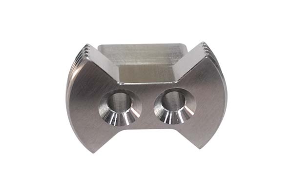
If you are designing a part for aluminum die casting, one question always comes up: how thin can I go? Push walls too thin, and you risk defects like incomplete filling or cold shuts. Stay too thick, and you waste material, add weight, and increase cycle time. There is no single number that works for every part. The minimum wall thickness depends on part size, complexity, and your production equipment.
Key takeaways
- Industry experts agree on a number: 0.5mm is the theoretical lower limit for aluminum die casting.
- The theoretical limit means little if your part cannot be made reliably. Seven factors determine what thickness you can actually achieve.
- The minimum wall thickness for aluminum die casting is not a single number.
What Is the Theoretical Minimum Wall Thickness?
Industry experts agree on a number: 0.5mm is the theoretical lower limit for aluminum die casting. Below this thickness, molten aluminum simply cannot flow reliably through narrow mold cavities before freezing.
Why 0.5mm?
Viscosity matters. Aluminum alloys like ADC12 have higher viscosity than zinc or magnesium. They do not flow as easily. When you try to push molten aluminum through a gap smaller than 0.5mm, it cools and solidifies before filling the cavity completely.
Pressure drops. In very thin sections, the pressure required to force metal through increases exponentially. Most die casting machines cannot maintain enough pressure at the flow front to keep metal moving.
Heat loss. Thin sections lose heat fast. The metal cools below its freezing point before the cavity fills, creating cold shuts and incomplete features.
Has Anyone Actually Achieved 0.5mm?
Yes—but only in very specific conditions.
Lab conditions: With perfect temperature control, optimal alloys, and simple geometries, researchers have produced test parts at 0.5mm.
Production examples: In high-end electronics, some components have been made at 0.55mm. These parts are tiny (surface area under 10 cm²) and simple—no deep cavities, no complex features.
Mass production reality: For most commercial applications, the practical minimum is 1.0–1.5mm. This range balances thin-wall benefits with reliable production.
What Factors Determine Your Actual Minimum Thickness?
The theoretical limit means little if your part cannot be made reliably. Seven factors determine what thickness you can actually achieve.
Casting Area: Size Matters
Larger parts need thicker walls. A small sensor housing can go thinner than a large automotive panel.
| Surface Area | Typical Minimum Thickness |
|---|---|
| Under 10 cm² | 0.8–1.0mm |
| 10–50 cm² | 1.0–1.2mm |
| Over 50 cm² | 1.2–1.5mm |
Why: In large areas, metal must travel farther to fill the cavity. It cools along the way. Thicker walls keep it flowing.
Design tip: If you need ultra-thin sections (under 1mm), keep them small—under 20 cm². Use gradual transitions (1:5 slope) from thin to thick areas.
Structural Complexity: Simple Is Easier
Complex geometries disrupt flow. Deep cavities, narrow slits, and undercuts all make filling harder.
Problem features:
- Cavities deeper than 5mm
- Slits narrower than 1.5mm
- Multiple undercuts
- Sharp corners
Each of these features forces metal to change direction, slow down, or split into multiple flow fronts. All increase the risk of incomplete filling.
Design tip: For thin walls, keep geometry simple. If you need deep cavities, add diversion ribs (0.8mm thick) to guide flow. Replace narrow slits with wider openings (at least 1.5mm).
Strength Requirements: Thin Must Be Strong
If your part carries load, thin walls may not work—even if they fill properly.
The problem: A 1.0mm wall has less than half the strength of a 1.5mm wall. For load-bearing applications, that difference matters.
The solution: Use stiffeners. Ribs add strength without thickening the whole wall. A good rule: stiffener height = 3× wall thickness. For a 1.0mm wall, 3mm ribs double bending resistance.
Critical areas: Identify high-stress points and keep them thicker (1.5–2.0mm). Use thin walls only in non-load-bearing sections.
Process Capability: Your Equipment Sets Limits
Modern machines with precise control can go thinner than old equipment.
What you need for thin walls:
- High injection speed (4–5 m/s) to fill before freezing
- Closed-loop pressure control (accuracy ±1MPa)
- Real-time monitoring to catch deviations
- High clamping force to keep mold closed under pressure
Mold quality matters too:
- Polished cavities (Ra ≤0.8μm) reduce friction
- Good cooling channels maintain temperature
- Proper venting lets air escape
Design tip: Know your equipment. If you are using older machines, add 0.2–0.3mm to the minimum thickness from tables.
Surface Treatment Needs: Allow for Material Removal
If your part needs plating, anodizing, or machining, you must leave extra material.
Typical allowances:
- Plating: 0.1–0.2mm total (both sides)
- Anodizing: 0.02–0.05mm (minimal, but changes dimensions)
- Machining: 0.2–0.5mm depending on feature
The risk: Start with a 1.0mm wall, remove 0.2mm for plating, and you have 0.8mm left. If that is below the minimum for your part, you get scrap.
Design tip: For parts needing surface treatment, set minimum wall thickness to ≥1.2mm. This gives you room for processing.
Alloy Selection: Some Flow Better
Not all aluminum alloys are equal. Silicon content determines flowability.
| Alloy | Silicon Content | Flowability | Minimum Thickness |
|---|---|---|---|
| ADC12 | 9.5–12% | Excellent | 0.55mm (lab) / 1.0mm (production) |
| A380 | 7.5–9.5% | Good | 1.0mm (production) |
| A356 | 6.5–7.5% | Moderate | 1.2mm (production) |
| 6061 | 0.4–0.8% | Poor | Not recommended for thin walls |
Why: Silicon improves fluidity. High-silicon alloys like ADC12 fill thin sections better than low-silicon alloys like 6061.
Design tip: For thin walls (under 1.2mm), specify ADC12 or equivalent high-flow alloy. Avoid 6061 and other low-silicon alloys for thin sections.
Mold Temperature Control: Heat Helps Flow
Hot molds keep metal flowing longer.
Standard practice: Mold temperature around 200°C for aluminum.
For thin walls: Increase to 220–250°C. This slows cooling in thin sections, giving metal more time to fill.
The tradeoff: Higher temperatures increase cycle time slightly and may cause other issues like solder. But for thin walls, the tradeoff is worth it.
How Do You Determine the Right Thickness for Your Part?
Follow this four-step framework to set your minimum wall thickness.
Step 1: Start with Surface Area
Use the table below as your baseline:
| Surface Area | Starting Minimum (ADC12) |
|---|---|
| ≤10 cm² | 0.8–1.0mm |
| 10–50 cm² | 1.0–1.2mm |
| >50 cm² | 1.2–1.5mm |
Step 2: Adjust for Complexity
Add 0.2–0.3mm if your part has:
- Cavities deeper than 5mm
- Slits narrower than 1.5mm
- More than 2 undercuts
- Multiple changes in direction
No adjustment needed for simple, flat parts.
Step 3: Account for Function
Non-load-bearing (covers, housings): Keep adjusted thickness.
Load-bearing (brackets, supports): Add 0.3–0.5mm to adjusted thickness.
Surface treatment required: Add 0.2mm total allowance.
Step 4: Test and Validate
Even the best calculations need real-world verification.
- Make prototypes (10–20 parts at your calculated thickness)
- Inspect for defects (visual check, X-ray for internal issues)
- Test performance (strength, impact, pressure if applicable)
- Adjust if needed (±0.1mm increments until defects disappear)
Real example: A manufacturer designed a 1.0mm housing for a 30 cm² part. First prototypes had 30% cold shuts. Increasing thickness to 1.2mm eliminated defects. The 0.2mm addition cost $0.15 more per part but saved 30% scrap.
What Common Mistakes Cause Thin-Wall Failures?
Avoid these three frequent errors.
Mistake 1: Chasing Ultra-Thin Without Reason
The problem: Designing a 0.6mm wall for a 50 cm² part because “thin is better.” Result: 80% scrap from undercasting.
The fix: Match thickness to part size. Use the practical minimum, not the theoretical limit. For large parts, 1.2–1.5mm is the real-world minimum.
Mistake 2: Ignoring Thickness Transitions
The problem: A part with 1.0mm walls in one section and 2.5mm in another. Thick sections cool slowly; thin sections cool fast. The mismatch creates shrinkage and distortion.
The fix: Keep thickness variation under ±20%. If one area must be thicker, use gradual transitions (1:5 slope minimum). This means a 1.0mm section should connect to a 1.2mm section, not directly to 2.5mm.
Mistake 3: Forgetting Stiffeners in Load-Bearing Parts
The problem: A 1.0mm thick automotive bracket fails under load because it has no ribs. The designer assumed thin would work.
The fix: Add stiffeners along load paths. Height = 3× wall thickness. Space them at 10–15× wall thickness intervals. For a 1.0mm wall, use 3mm tall ribs every 10–15mm.
How to write a spec that gets priced correctly
A drawing is a contract. If it leaves a number open, the shop fills that number in with its own default. The default is rarely the one you had in mind. Put these five lines on every RFQ and most of the back-and-forth disappears before it starts.
- 3D model with the parting line marked
- Alloy grade and the standard it meets
- Wall thickness and draft on every face
- Machining allowance on the faces that will be cut
- Pressure tightness or porosity class
The point is not paperwork. Each line removes a decision the shop would otherwise make for you. A complete RFQ comes back priced. An incomplete one comes back guessed.
What actually drives the price
Buyers usually push on material because it is the line they can see. In practice the material is rarely the biggest number on a quote. These five lines decide most of it:
- die steel and cavity count
- part weight and wall section
- draft and slide count
- porosity requirement
- machining allowance
Ask for the quote split by line. A supplier who cannot break it down is guessing, and you will pay for the guess. The line you can usually renegotiate is the tolerance band, not the raw material.
Problems you will meet, and the fix
Every process has a failure mode it prefers. The same four show up again and again on this kind of work, and none of them are mysteries once you know what to look for.
- Cold shuts where two flow fronts meet
- Porosity that shows up only after machining
- Soldering on a hot spot in the die
- Shrinkage voids in a heavy section
Catch the fault on the first part, not the hundredth. A first-article check costs an hour. A bad batch costs the whole order. Write the check into the purchase order so nobody has to remember it.
What to check on the first article
The first article is the cheapest inspection you will ever buy. Use it properly and the rest of the run becomes boring, which is exactly what you want.
- Every dimension on the drawing, with the measured value written beside it.
- The material certificate, matched to the heat or lot number on the parts.
- The finish against the sample you approved, under the same light.
- Fit against the mating part, assembled rather than measured.
- Packaging, because parts that arrive damaged were never in tolerance.
Check in this order: datums, then mating features, then cosmetic faces. If the datums are wrong, every number after them is noise. Keep the report on file. When a problem shows up in month six, that document is the only thing that tells you what changed.
How to compare two quotes fairly
Two numbers are not comparable unless the scope matches. Line them up before you decide, because a low number with three gaps is not a low number.
Same drawing, same material, same finish, same inspection. Anything else is a different job wearing the same part number. Then look at what each quote leaves out. Freight, packaging, certificates and tooling are the usual gaps.
Ask each supplier to state their assumptions in writing. The one who does is usually the one who has run the process before.
FAQ About Aluminum Die Casting Wall Thickness
Can I achieve 0.4mm wall thickness in aluminum die casting?
No. 0.4mm is below the theoretical limit of 0.5mm. Even with perfect conditions, aluminum will freeze before filling a 0.4mm cavity. For ultra-thin applications, consider zinc die casting (can achieve 0.3mm) or machining from solid.
How does wall thickness affect cost?
Thinner walls reduce material cost—a 1.0mm part uses 30% less aluminum than a 1.5mm part of the same size. But thin walls may increase process costs (tighter control, higher scrap if not optimized). For high volumes (over 100,000 parts), the material savings usually outweigh process costs, making 1.0–1.2mm the most economical range.
What is the thinnest wall achievable in mass production?
For reliable mass production (scrap under 5%), the practical minimum is 1.0mm for small parts (under 10 cm²) and 1.2mm for medium parts (10–50 cm²). Large parts rarely go below 1.5mm in production.
Do ribs count as wall thickness for minimum calculations?
No. Ribs are separate features. You can have 1.0mm walls with 2mm ribs. The rib thickness is governed by different rules (typically 0.8× wall thickness for the rib base). Ribs help strengthen thin walls without thickening the whole part.
Can I mix thin and thick sections in one part?
Yes, but use gradual transitions. A sudden jump from 1.0mm to 3.0mm creates a hot spot that will cause shrinkage defects. Taper the transition over at least 5× the thickness difference. For a 2mm difference, make the transition at least 10mm long.
Which aluminum alloy is best for thin walls?
ADC12 (or equivalent A380) is the standard choice. Its high silicon content (9.5–12%) gives excellent flowability. For ultra-thin applications (under 1.0mm), some specialized alloys with even higher silicon (up to 17%) exist, but they are more expensive and less common.
The minimum wall thickness for aluminum die casting is not a single number. The theoretical limit is 0.5mm, but this is achievable only in labs with tiny, simple parts. For real-world production:
- Small parts (under 10 cm²): 0.8–1.0mm
- Medium parts (10–50 cm²): 1.0–1.2mm
- Large parts (over 50 cm²): 1.2–1.5mm
Seven factors determine where your part falls:
- Surface area (larger = thicker)
- Complexity (complex = thicker)
- Strength needs (load-bearing = thicker)
- Process capability (better equipment = thinner possible)
- Surface treatment (plating/machining = add allowance)
- Alloy type (high-silicon = thinner possible)
- Mold temperature (hotter molds = thinner possible)
Use the four-step framework to set your target:
- Start with surface area baseline
- Adjust for complexity
- Account for function and treatment
- Test and validate
Avoid common mistakes: don’t chase ultra-thin without reason, use gradual thickness transitions, and add stiffeners for load-bearing parts.
The goal is not the thinnest possible wall—it is the thinnest wall that works reliably for your specific part. Balance thinness with producibility, and you will get lightweight parts that perform well and cost less.
Our solution for Minimum Thinnest Wall Thickness
YiguProto runs die casting in house, from a single prototype to a production batch. We quote the process, the material and the finish as separate lines, so you can see where the money goes instead of arguing with one number.
Send a STEP file or a drawing and you get a DFM report in one to two business days. It flags the features that add cost and the features that will not hold tolerance on the process you picked.
Every order ships with an inspection report on the features you call out. If a part misses, we make it again. Ready to price a part? Start with a free quote and DFM review, or read more about our die casting. You can also talk to an engineer before you commit to a drawing.
FAQ about Minimum Thinnest Wall Thickness
What should I check before approving the parts?
Datums first, then the features that mate, then the cosmetic faces. Ask for a dimensional report, a material certificate and a finish sample. A part can be inside every tolerance and still not fit, so assemble one before you sign.
What files do you need in order to quote?
A STEP file plus a PDF drawing that carries the same revision letter. The model carries the geometry and the drawing carries the intent. When the two disagree, the shop picks one, and it is never the one you meant.
How much does Minimum Thinnest Wall Thickness cost?
Price comes from five lines: material, machine or tool time, setup, finishing and inspection. The material itself is usually the smallest of them. Send a drawing and we will split the quote so you can see which line is doing the damage.
How long does a first article take?
Usually a few business days once the drawing is frozen, and longer if tooling is involved. The date we give you is the date we confirm in writing, not the date we hope for.
What is the lead time for Minimum Thinnest Wall Thickness?
Expect 20 to 30 business days including die build. Tooling, material stock and the finishing queue all move that number, so we confirm the date in writing before the run starts rather than after.
Does the process work for prototypes as well as production?
Yes, and that is usually the point. Running the prototype on the production process removes a whole class of surprises, because the part you test is made the same way as the part you sell.
The short version
Minimum Thinnest Wall Thickness rewards the buyer who reads the data sheet and the drawing together. Pick the option for the property that matters, not for the price per kilo.
Tighten only what mates. Test a sample before the run. Then let the process do the rest.