
Die Casting
What Determines Shrinkage Rate of Die Casting Aluminum and How to Control It?
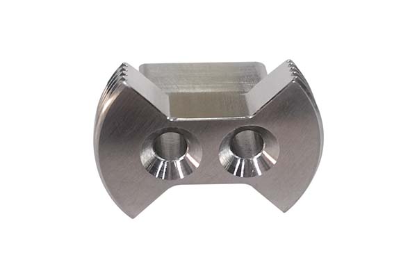
If you design or manufacture aluminum die castings, you know that parts never come out of the mold exactly the size of the cavity. They shrink. The question is: how much? The shrinkage rate of die casting aluminum determines whether your 100 mm design becomes a 99.45 mm part or a 98.5 mm reject. It is not a fixed number. Alloy choice, part geometry, mold design, and process parameters all play a role.
What Are the Typical Ranges of Aluminum Die Casting Shrinkage?
Shrinkage is not one number—it spans two ranges depending on complexity and alloy.
Base Range: Conventional Scenarios
For most standard applications, shrinkage rate falls between 0.5% and 1%.
Typical alloys: ADC12, A380 (80% of die casting applications)
Typical parts: Automotive non-load-bearing brackets, instrument panel housings, smartphone charger shells, router casings
Example: A380 aluminum has a shrinkage rate of approximately 0.55%. A 100 mm long part will shrink to:
100 mm × (1 – 0.0055) = 99.45 mm
That 0.55 mm change is predictable and easily compensated in the mold design.
Expansion Range: Complex or Special Scenarios
For complex parts or specialty alloys, shrinkage expands to 1.5% to 5%.
What drives this:
- Complex structures: Uneven cooling creates localized stress. An engine water jacket with intricate internal channels may shrink 1.8–2.2%.
- Specialty alloys: High alloying element content (copper, magnesium) increases atomic gaps. Al-Cu-Mg aerospace alloys can shrink 3–5%.
Example: An Al-Cu-Mg alloy part (4–5% Cu) may have a 3% shrinkage rate. A 100 mm design becomes 97 mm—a much larger change that requires precise compensation.
What Factors Determine the Shrinkage Rate?
Four interrelated factors control how much aluminum shrinks.
Alloy Composition
Alloying elements change the aluminum matrix’s atomic structure. More alloying elements = larger atomic gaps = more shrinkage.
| Alloy | Key Elements | Shrinkage Rate |
|---|---|---|
| ADC12 | Si 9.5–12%, Cu 1.5–3.5% | 0.6–0.8% |
| A380 | Si 7.5–9.5%, Cu 3–4% | 0.5–0.7% |
| Al-Cu-Mg | Cu 4–5%, Mg 1.5–2.5% | 3–5% |
Rule of thumb: Each 1% increase in copper or magnesium raises shrinkage by 0.2–0.3%.
Casting Structure
Complex structures cause uneven cooling. Thick sections (hot spots) cool slowly and shrink more. Thin sections cool fast and shrink less.
| Part Type | Shrinkage Rate |
|---|---|
| Simple flat plate, 5 mm thick | 0.5–0.6% |
| Gearbox housing (2 mm walls + 10 mm flanges) | 1.2–1.5% |
The difference: Complex parts have 0.5–2% higher shrinkage than simple parts of the same alloy.
Mold Design and Material
Molds either restrict or allow shrinkage.
Mold material: H13 tool steel (low thermal expansion) lowers shrinkage by 0.1–0.2% compared to cast iron molds (higher expansion).
Cooling system: Optimized multi-zone cooling reduces shrinkage variation by 30–40%.
Example: An aluminum laptop frame mold:
- H13 steel + multi-zone cooling → shrinkage 0.5–0.7%
- Cast iron + single cooling channel → shrinkage 0.7–0.9%
Process Parameters
Your machine settings directly affect shrinkage.
| Parameter | Effect on Shrinkage |
|---|---|
| Injection pressure | Higher pressure (80–120 MPa) compacts metal, reduces shrinkage; lower pressure (50–70 MPa) increases it |
| Holding time | Longer time (10–20 s) feeds additional metal to compensate; shorter time (5–8 s) leaves voids |
| Mold temperature | Higher (200–250°C) slows cooling, increases shrinkage; lower (150–180°C) accelerates cooling, reduces it |
Quantified effects:
- Increasing pressure from 70 MPa to 100 MPa lowers shrinkage 0.15–0.25%
- Extending hold from 8 s to 15 s reduces shrinkage 0.1–0.15%
How Do You Control Shrinkage in Practice?
Pre-Production: Mold Compensation Design
This is the most effective method—design the mold to account for shrinkage before any metal is poured.
Step 1: Determine target shrinkage rate
Based on alloy and part complexity, select from known ranges:
- A380 simple part: 0.55%
- A380 complex part (internal channels): 0.7%
- Al-Cu-Mg aerospace part: 2.0%
Step 2: Calculate mold enlargement
Mold dimension = Final part dimension × (1 + Shrinkage rate)
For a 100 mm part with 0.55% shrinkage:
100 mm × 1.0055 = 100.55 mm mold cavity
Step 3: Localize adjustments
Hot spots (thick ribs) need more compensation—add 0.1–0.3% in those areas. A 10 mm thick rib might need 0.7% compensation while 5 mm walls get 0.55%.
In-Process: Parameter Optimization
Fine-tune your machine settings:
Injection pressure:
- Standard alloys (ADC12, A380): 80–100 MPa
- High-alloy parts: 100–120 MPa
Holding time:
- Set to 1.5–2× solidification time
- 5 mm thick part: 12 seconds
- 8 mm thick part: 18 seconds
Mold temperature:
- Maintain 180–220°C for aluminum
- Keep variation under ±10°C across the mold
Post-Production: Test and Calibrate
Trial casting: Produce 5–10 parts, measure key dimensions with CMM. Calculate actual shrinkage.
If a part designed for 0.55% shrinkage actually shrinks 0.6%, adjust the mold by 0.05% (enlarge cavity slightly).
Statistical monitoring: In production, sample 3–5% of parts per batch. If variation exceeds ±0.1%, recalibrate (e.g., raise mold temperature 10°C).
Real-World Applications by Industry
| Industry | Parts | Alloy & Shrinkage | Control Measures |
|---|---|---|---|
| Automotive | Engine blocks, transmission housings | A380: 0.55–0.7%; Al-Cu-Mg: 1.8–2.2% | H13 molds with multi-zone cooling; 100–120 MPa pressure; 15–20 s hold |
| Consumer electronics | Phone frames, tablet backs | ADC12: 0.6–0.8% | Precision mold compensation (0.7% uniform); 80–90 MPa pressure; 10–12 s hold |
| Aerospace | Lightweight structural brackets | Al-Mg-Si: 1.2–1.5% | 3 iteration trial casting to calibrate; mold temperature 200±5°C |
| Home appliances | Compressor shells, washing machine drums | A356: 0.5–0.6% | Simple mold design (avoid uneven cooling); 70–80 MPa pressure; 8–10 s hold |
How to write a spec that gets priced correctly
A drawing is a contract. If it leaves a number open, the shop fills that number in with its own default. The default is rarely the one you had in mind. Put these five lines on every RFQ and most of the back-and-forth disappears before it starts.
- 3D model with the parting line marked
- Alloy grade and the standard it meets
- Wall thickness and draft on every face
- Machining allowance on the faces that will be cut
- Pressure tightness or porosity class
The point is not paperwork. Each line removes a decision the shop would otherwise make for you. A complete RFQ comes back priced. An incomplete one comes back guessed.
What actually drives the price
Buyers usually push on material because it is the line they can see. In practice the material is rarely the biggest number on a quote. These five lines decide most of it:
- die steel and cavity count
- part weight and wall section
- draft and slide count
- porosity requirement
- machining allowance
Ask for the quote split by line. A supplier who cannot break it down is guessing, and you will pay for the guess. The line you can usually renegotiate is the tolerance band, not the raw material.
Problems you will meet, and the fix
Every process has a failure mode it prefers. The same four show up again and again on this kind of work, and none of them are mysteries once you know what to look for.
- Cold shuts where two flow fronts meet
- Porosity that shows up only after machining
- Soldering on a hot spot in the die
- Shrinkage voids in a heavy section
Catch the fault on the first part, not the hundredth. A first-article check costs an hour. A bad batch costs the whole order. Write the check into the purchase order so nobody has to remember it.
What to check on the first article
The first article is the cheapest inspection you will ever buy. Use it properly and the rest of the run becomes boring, which is exactly what you want.
- Every dimension on the drawing, with the measured value written beside it.
- The material certificate, matched to the heat or lot number on the parts.
- The finish against the sample you approved, under the same light.
- Fit against the mating part, assembled rather than measured.
- Packaging, because parts that arrive damaged were never in tolerance.
Check in this order: datums, then mating features, then cosmetic faces. If the datums are wrong, every number after them is noise. Keep the report on file. When a problem shows up in month six, that document is the only thing that tells you what changed.
How to compare two quotes fairly
Two numbers are not comparable unless the scope matches. Line them up before you decide, because a low number with three gaps is not a low number.
Same drawing, same material, same finish, same inspection. Anything else is a different job wearing the same part number. Then look at what each quote leaves out. Freight, packaging, certificates and tooling are the usual gaps.
Ask each supplier to state their assumptions in writing. The one who does is usually the one who has run the process before.
Scaling from one part to a batch
The first part teaches you the process. The hundredth teaches you the process cost.
Watch three things as volume grows: setup amortisation, tool wear, and how much hand work the finish still needs. If the unit price barely moves between ten and a hundred, the cost sits in material or in hand work, not in setup. Ask which, because only one of them is negotiable.
Lead time behaves the same way. A one-off is scheduled around other jobs. A repeat order is scheduled around your forecast. Give the shop a forecast and the lead time gets shorter, not longer.
How to read a supplier's quote
A quote is a short document with a long shadow. Four things in it decide whether the job runs smoothly, and only one of them is the price.
- The scope line. It should name the process, the material and the finish, not just the part.
- The tolerance basis. General tolerance or the drawing, and which standard it follows.
- The exclusions. Tooling, freight, certificates and inspection are the usual omissions.
- The validity date. Material prices move, and an open-ended quote is a promise nobody can keep.
Read the exclusions before you read the total. A quote that leaves out tooling is not cheaper. It is a quote for a different job.
What to send with the first order
The first order sets the pattern for every order after it. Send a complete package once and the shop files it, and the second order takes a fraction of the time.
- A STEP or native model plus a PDF drawing carrying the same revision letter.
- The material callout by standard number, not by trade name.
- The finish and the exact faces it applies to.
- Any test the part must pass: fit, seal, drop, salt spray, dielectric.
- A contact who can answer a question inside one working day.
Then write down what was agreed. An email that confirms the material, the finish and the date is worth more than a longer purchase order that leaves them open.
When this is the wrong choice
A good supplier tells you when the process does not fit. These are the cases where we say so.
- The volume is so low that setup costs more than the parts are worth.
- The tolerance is tighter than the process can hold without a second operation.
- The geometry cannot be made without a tool feature that will not pay back.
- The material you need is not available in the form the process requires.
- The schedule is shorter than the tooling or setup time, and nobody has said so yet.
None of these are refusals. They are reasons to look at a different route, and the earlier that conversation happens the cheaper it is. The most expensive mistake in manufacturing is a process chosen before the question was understood.
Planning the ramp from prototype to production
The gap between one good part and a thousand identical ones is a plan, not a machine. Three decisions close it.
First, freeze the design. Every change after tooling starts is a re-cut, and re-cuts are where schedules go. Second, decide the inspection level. A prototype is checked by eye; a production part is checked against a report. Third, agree the change process in writing, including who pays for it.
Write the ramp down as dates and owners, not as intentions. A ramp plan with three names and three dates is worth more than a page of good intentions.
FAQ About Aluminum Die Casting Shrinkage
Why does shrinkage vary between simple and complex parts?
Complex parts have uneven cooling. Thick sections (hot spots) cool slowly, allowing more time for atomic rearrangement and greater shrinkage. Thin sections cool fast, limiting shrinkage. This localized difference pushes overall rate 0.5–2% higher than simple, uniformly thick parts.
Can I use the same shrinkage rate for all aluminum alloys?
No. Alloy composition drives shrinkage:
- Standard alloys (ADC12, A380): 0.5–0.8% (low alloying elements)
- High-strength alloys (Al-Cu-Mg): 1.2–5% (high alloying elements)
Always reference alloy-specific data or conduct trial casting. Using A380 shrinkage for Al-Cu-Mg would produce parts undersized by 2–4 mm—total scrap.
How much mold compensation for a 200 mm A380 part?
A380 typical rate: 0.55%.
Mold length = 200 mm × (1 + 0.0055) = 201.1 mm
For complex A380 parts (internal channels), use 0.7%:
201 mm × 1.007 = 201.4 mm
Always verify with 3–5 trial parts and adjust for actual production conditions.
Can process parameters fully compensate for poor mold design?
No. If the mold does not account for shrinkage in its dimensions, no amount of pressure or temperature adjustment will fix it. Mold compensation is the primary control; parameters fine-tune within that range.
How do I know if my shrinkage control is working?
Monitor three things:
- First article inspection: Trial parts within ±0.1 mm of target?
- Production sampling: 3–5% of parts per batch consistently within tolerance?
- Trend analysis: Is shrinkage drifting over time (mold wear, parameter drift)?
If any answer is no, investigate and correct.
The shrinkage rate of die casting aluminum is not a fixed property—it is a dynamic result of alloy, geometry, mold, and process.
- Alloy choice: Standard alloys (ADC12, A380) shrink 0.5–0.8%; high-alloy grades can shrink 3–5%
- Part complexity: Complex structures add 0.5–2% to shrinkage
- Mold design: H13 steel and optimized cooling reduce shrinkage 0.1–0.2%
- Process parameters: Higher pressure, longer hold, optimal mold temperature all reduce shrinkage
Control requires a three-stage approach:
- Pre-production: Mold compensation based on target shrinkage
- In-process: Parameter optimization (pressure, hold, temperature)
- Post-production: Trial casting, measurement, and calibration
Get it right, and parts come out of the mold within tolerance, assemblies fit, and scrap stays low. Get it wrong, and no amount of post-processing can fix dimensions that started wrong.
Master shrinkage control, and you master aluminum die casting.
Our solution for Determines Shrinkage Rate
YiguProto runs die casting in house, from a single prototype to a production batch. We quote the process, the material and the finish as separate lines, so you can see where the money goes instead of arguing with one number.
Send a STEP file or a drawing and you get a DFM report in one to two business days. It flags the features that add cost and the features that will not hold tolerance on the process you picked.
Every order ships with an inspection report on the features you call out. If a part misses, we make it again. Ready to price a part? Start with a free quote and DFM review, or read more about our die casting. You can also talk to an engineer before you commit to a drawing.
FAQ about Determines Shrinkage Rate
How long does a first article take?
Usually a few business days once the drawing is frozen, and longer if tooling is involved. The date we give you is the date we confirm in writing, not the date we hope for.
What files do you need in order to quote?
A STEP file plus a PDF drawing that carries the same revision letter. The model carries the geometry and the drawing carries the intent. When the two disagree, the shop picks one, and it is never the one you meant.
Does the process work for prototypes as well as production?
Yes, and that is usually the point. Running the prototype on the production process removes a whole class of surprises, because the part you test is made the same way as the part you sell.
How much does Determines Shrinkage Rate cost?
Price comes from five lines: material, machine or tool time, setup, finishing and inspection. The material itself is usually the smallest of them. Send a drawing and we will split the quote so you can see which line is doing the damage.
What is Determines Shrinkage Rate used for?
Determines Shrinkage Rate turns up wherever the part has to do a real job at a predictable cost: brackets, housings, fixtures, covers and the fittings that hold them together. The honest test is whether the properties match the load and the environment, not whether the material is fashionable.
What material should I specify?
Specify by standard, not by trade name. A trade name can change under you between two orders; a standard number cannot. Then add the one property that actually decides the part, whether that is strength, heat resistance or chemical exposure.
The short version
Determines Shrinkage Rate rewards the buyer who reads the data sheet and the drawing together. Pick the option for the property that matters, not for the price per kilo.
Tighten only what mates. Test a sample before the run. Then let the process do the rest.