
3D Printing
How Is 3D Printing Reshaping Aircraft Engine Design?
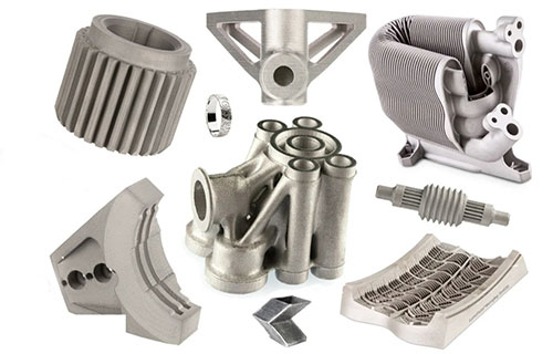
3D printing is transforming aircraft engine manufacturing by enabling unprecedented design freedom. This technology allows for the production of complex, integrated components like fuel nozzles and turbine blades that are lighter, stronger, and more efficient than those made with traditional methods.
Key takeaways
- The core advantages of additive manufacturing align perfectly with the relentless aerospace goals of weight reduction, performance enhancement, and efficiency gains.
- The application of AM in aircraft engines follows a clear progression: starting with non-critical, static components and moving toward high-stress, rotating parts as confidence and technology mature.
- Adopting AM for flight-critical parts is not without significant hurdles, which the industry is methodically addressing.
- The path forward is built on process digitization, advanced quality assurance, and new design methodologies.
Why Use 3D Printing for Engines?
The core advantages of additive manufacturing align perfectly with the relentless aerospace goals of weight reduction, performance enhancement, and efficiency gains.
- Part Consolidation: This is perhaps the most famous benefit. A classic example is the CFM LEAP engine fuel nozzle. Traditionally, this component was assembled from 20 individually cast and machined parts, brazed and welded together. This assembly was prone to leaks and required extensive quality checks. GE Aviation redesigned it as a single, unified piece printed via Direct Metal Laser Melting (DMLM). The result: a 25% lighter part that is five times more durable and eliminates all assembly joints and potential leak paths.
- Lightweight, Optimized Structures: AM allows for the creation of internal lattice structures and hollow, organic forms that are impossible to machine. Rolls-Royce, for instance, has developed the Advance3 engine core which features a 3D-printed front bearing housing with 48 aerodynamically shaped “curtains” inside for better airflow. This part consolidates what was previously over 10 components into one, reducing weight and simplifying assembly.
- Material Efficiency and Advanced Alloys: Traditional machining of a titanium billet can waste up to 95% of the expensive raw material. AM is an additive process, typically using only the powder needed for the part and a small support structure, with unused powder being recyclable. This makes it economically viable to use high-performance, difficult-to-machine alloys like Titanium Aluminide (TiAl). TiAl is about 50% lighter than traditional nickel superalloys and maintains strength at high temperatures, making it ideal for low-pressure turbine blades, such as those in the GE9X engine.
The following table summarizes the transformative impact of these advantages:
| Design Goal | Traditional Method Limitation | 3D Printing Solution | Real-World Impact |
|---|---|---|---|
| Reduce Part Count & Assembly | Complex assemblies with brazes/welds are failure points. | Print as a single, integrated component. | Increased reliability, reduced inspection, lower inventory. |
| Maximize Strength-to-Weight | Solid machining or casting adds unnecessary weight. | Internal lattices & topology optimization. | Lighter engines, directly improving fuel efficiency (≈1% SFC improvement per 1% weight saved). |
| Utilize Advanced Materials | High waste makes exotic alloys prohibitively expensive. | Near-net-shape production minimizes waste. | Enables use of TiAl and CMCs (Ceramic Matrix Composites) for higher-temperature operation. |
What Parts Are Being Printed Today?
The application of AM in aircraft engines follows a clear progression: starting with non-critical, static components and moving toward high-stress, rotating parts as confidence and technology mature.
- Brackets, Housings, and Ducts: These are common entry points. Air inlet ducts, sensor housings, and various mounting brackets are ideal because they often have complex shapes for optimal airflow but bear relatively low loads. Their production via AM simplifies supply chains and allows for rapid design iterations.
- Fuel System Components: The fuel nozzle is the poster child for AM in aerospace. Beyond the LEAP nozzle, companies are printing fuel swirlers and manifolds. These parts benefit immensely from consolidation (eliminating seals) and the ability to create precise, internal flow channels that improve fuel-air mixing for cleaner combustion.
- Heat Exchangers and Combustor Parts: The combustor liner and heat exchanger cores require intricate networks of cooling channels to survive extreme temperatures. AM can create these conformal cooling channels that follow the part’s surface more efficiently than drilled holes, leading to better temperature management and longer part life.
- Turbine Blades and Vanes: This is the frontier. Printing high-pressure turbine blades with complex, serpentine cooling channels is a major focus. These channels can be optimized for maximum heat transfer, allowing engines to run hotter and more efficiently. GE’s GE9X engine incorporates 3D-printed TiAl low-pressure turbine blades, showcasing the move into critical rotating components.
Case in Point: The GE9X Engine:
This engine, powering the Boeing 777X, contains over 300 additive manufactured parts. This includes fuel nozzles, T25 sensor housings (the first FAA-certified 3D-printed part in a commercial jet engine), heat exchangers, and the TiAl low-pressure turbine blades. This widespread adoption demonstrates a full transition from prototyping to certified, serial production, contributing to the GE9X’s claim of 10% better fuel efficiency than its predecessor.
What Are the Key Challenges?
Adopting AM for flight-critical parts is not without significant hurdles, which the industry is methodically addressing.
- Material Properties and Consistency: The microstructure of a 3D-printed metal part is not the same as a forged one. It can have anisotropic properties (different strength depending on orientation) and internal porosity. The solution lies in precise process control (laser power, scan speed, hatch spacing) and post-processing. Hot Isostatic Pressing (HIP) is a critical step that uses high heat and pressure to close internal pores, and specific heat treatments are developed to achieve the desired grain structure and mechanical properties.
- Verification and Certification: This is the biggest barrier to entry. Aviation authorities like the FAA and EASA require deterministic certification—proof that every part will perform as specified. For AM, this means moving from a “test and qualify” model (used for forgings) to a “qualify the process” model. Manufacturers must demonstrate that their digital thread—from powder feedstock specification, to machine calibration, to build parameters, to post-processing—is repeatable, traceable, and produces consistent results. This requires massive investment in in-situ monitoring (sensors watching the print) and non-destructive testing (NDT) like micro-CT scanning.
- Production Speed and Cost at Scale: While AM reduces waste, the machine time per part is high, and industrial metal AM systems are capital-intensive. For high-volume parts like turbine blades, the cost-per-part must compete with investment casting. The industry response is multi-laser systems (4+ lasers in one machine), larger build volumes, and automated post-processing cells. The focus is on leveraging AM’s value where it’s greatest: for low-volume, high-complexity parts that are too expensive or impossible to make any other way.
How to write a spec that gets priced correctly
A drawing is a contract. If it leaves a number open, the shop fills that number in with its own default. The default is rarely the one you had in mind. Put these five lines on every RFQ and most of the back-and-forth disappears before it starts.
- File format and units, with the model exported in millimetres
- Process and material grade, not a trade name
- Critical features and the tolerance each one needs
- Surface finish and the faces it applies to
- Quantity for the pilot build and for the year
The point is not paperwork. Each line removes a decision the shop would otherwise make for you. A complete RFQ comes back priced. An incomplete one comes back guessed.
What actually drives the price
Buyers usually push on material because it is the line they can see. In practice the material is rarely the biggest number on a quote. These five lines decide most of it:
- build volume and orientation
- layer height and support structure
- material grade and colour
- post-processing and hand finishing
- quantity per build plate
Ask for the quote split by line. A supplier who cannot break it down is guessing, and you will pay for the guess. The line you can usually renegotiate is the tolerance band, not the raw material.
Problems you will meet, and the fix
Every process has a failure mode it prefers. The same four show up again and again on this kind of work, and none of them are mysteries once you know what to look for.
- Warping on long flat faces where the part lifts off the plate
- Layer lines showing through a cosmetic surface
- Support scars on a mating face nobody flagged
- Dimensional drift on thin walls after cooling
Catch the fault on the first part, not the hundredth. A first-article check costs an hour. A bad batch costs the whole order. Write the check into the purchase order so nobody has to remember it.
What to check on the first article
The first article is the cheapest inspection you will ever buy. Use it properly and the rest of the run becomes boring, which is exactly what you want.
- Every dimension on the drawing, with the measured value written beside it.
- The material certificate, matched to the heat or lot number on the parts.
- The finish against the sample you approved, under the same light.
- Fit against the mating part, assembled rather than measured.
- Packaging, because parts that arrive damaged were never in tolerance.
Check in this order: datums, then mating features, then cosmetic faces. If the datums are wrong, every number after them is noise. Keep the report on file. When a problem shows up in month six, that document is the only thing that tells you what changed.
How to compare two quotes fairly
Two numbers are not comparable unless the scope matches. Line them up before you decide, because a low number with three gaps is not a low number.
Same drawing, same material, same finish, same inspection. Anything else is a different job wearing the same part number. Then look at what each quote leaves out. Freight, packaging, certificates and tooling are the usual gaps.
Ask each supplier to state their assumptions in writing. The one who does is usually the one who has run the process before.
Scaling from one part to a batch
The first part teaches you the process. The hundredth teaches you the process cost.
Watch three things as volume grows: setup amortisation, tool wear, and how much hand work the finish still needs. If the unit price barely moves between ten and a hundred, the cost sits in material or in hand work, not in setup. Ask which, because only one of them is negotiable.
Lead time behaves the same way. A one-off is scheduled around other jobs. A repeat order is scheduled around your forecast. Give the shop a forecast and the lead time gets shorter, not longer.
How to read a supplier's quote
A quote is a short document with a long shadow. Four things in it decide whether the job runs smoothly, and only one of them is the price.
- The scope line. It should name the process, the material and the finish, not just the part.
- The tolerance basis. General tolerance or the drawing, and which standard it follows.
- The exclusions. Tooling, freight, certificates and inspection are the usual omissions.
- The validity date. Material prices move, and an open-ended quote is a promise nobody can keep.
Read the exclusions before you read the total. A quote that leaves out tooling is not cheaper. It is a quote for a different job.
What to send with the first order
The first order sets the pattern for every order after it. Send a complete package once and the shop files it, and the second order takes a fraction of the time.
- A STEP or native model plus a PDF drawing carrying the same revision letter.
- The material callout by standard number, not by trade name.
- The finish and the exact faces it applies to.
- Any test the part must pass: fit, seal, drop, salt spray, dielectric.
- A contact who can answer a question inside one working day.
Then write down what was agreed. An email that confirms the material, the finish and the date is worth more than a longer purchase order that leaves them open.
How Are These Challenges Being Solved?
The path forward is built on process digitization, advanced quality assurance, and new design methodologies.
- The Digital Thread and Process Qualification:
Leading companies are not just printing parts; they are certifying the entire digital workflow. Every batch of metal powder is tracked. Every build uses a locked and validated parameter set. In-situ monitoring systems using high-speed cameras and thermal sensors detect anomalies like spatter or lack-of-fusion in real-time, allowing for build correction or stoppage. This data-rich environment creates a digital twin of the manufacturing process, which is essential for certification. - Advanced Non-Destructive Evaluation (NDE):
Post-print inspection goes beyond traditional methods. Micro-CT (computed tomography) scanning is now standard. It creates a 3D X-ray model of the part, revealing internal pores or cracks as small as 10-20 microns. This allows for 100% inspection of internal features that were previously un-inspectable without destructive testing. - Design for Additive Manufacturing (DfAM):
Success requires rethinking design from the ground up. Engineers use generative design software to create organic, optimized shapes. They design self-supporting structures to minimize post-processing and consolidate assemblies into monolithic parts. This is a cultural and skillset shift as significant as the technological one.
Industry Benchmark – The FAA’s Approach:
The FAA has published Advisory Circular 20-168, which guides the certification of additively manufactured parts. It emphasizes a robust quality assurance system covering the entire process chain: material control, machine calibration, process validation, post-processing, and final part verification. This framework is what allows parts like the GE T25 sensor housing to fly on hundreds of aircraft today.
3D printing is no longer a futuristic concept for aircraft engines; it is a present-day production technology delivering measurable performance gains. The journey from a novel prototyping tool to a source of FAA-certified, flight-critical components has been driven by its unique ability to reduce weight, consolidate parts, and unlock designs that defy traditional manufacturing. While challenges in process control, certification, and economics at scale are real, the industry is meeting them head-on through digitization, advanced inspection, and a new DfAM mindset. The result is a new paradigm for engine design—one where complexity is free, and efficiency is fundamentally built into the geometry of every component. The future of aerospace propulsion is being printed, layer by precise layer.
Our solution for 3D Printing Reshaping Aircraft Engine
YiguProto runs 3D printing in house, from a single prototype to a production batch. We quote the process, the material and the finish as separate lines, so you can see where the money goes instead of arguing with one number.
Send a STEP file or a drawing and you get a DFM report in one to two business days. It flags the features that add cost and the features that will not hold tolerance on the process you picked.
Every order ships with an inspection report on the features you call out. If a part misses, we make it again. Ready to price a part? Start with a free quote and DFM review, or read more about our 3D printing. You can also talk to an engineer before you commit to a drawing.
FAQ about 3D Printing Reshaping Aircraft Engine
What tolerance can you hold on 3D Printing Reshaping Aircraft Engine?
The working default is ±0.1 mm on small features, ±0.3% on long spans. Tighter than that the process changes and so does the price, because every step tighter adds inspection time. Call out only the faces that mate with something else and leave the rest on the general tolerance.
What happens if a part is out of specification?
We measure it against the same drawing you approved and, if it misses, we make it again. What matters is that the report exists, because a disagreement without data is just an opinion.
How long does a first article take?
Usually a few business days once the drawing is frozen, and longer if tooling is involved. The date we give you is the date we confirm in writing, not the date we hope for.
What is the lead time for 3D Printing Reshaping Aircraft Engine?
Expect 2 to 5 business days for a first batch. Tooling, material stock and the finishing queue all move that number, so we confirm the date in writing before the run starts rather than after.
What should I check before approving the parts?
Datums first, then the features that mate, then the cosmetic faces. Ask for a dimensional report, a material certificate and a finish sample. A part can be inside every tolerance and still not fit, so assemble one before you sign.
How do I compare two quotes fairly?
Match the scope first: same drawing, same material, same finish, same inspection. Then read the exclusions. Freight, tooling and certificates are the usual gaps, and a low number with three gaps is not a low number.
The short version
3D Printing Reshaping Aircraft Engine rewards the buyer who reads the data sheet and the drawing together. Pick the option for the property that matters, not for the price per kilo.
Tighten only what mates. Test a sample before the run. Then let the process do the rest.