
3D Printing
How Can 3D Printing Solid Prototypes Revolutionize Your Product Development?
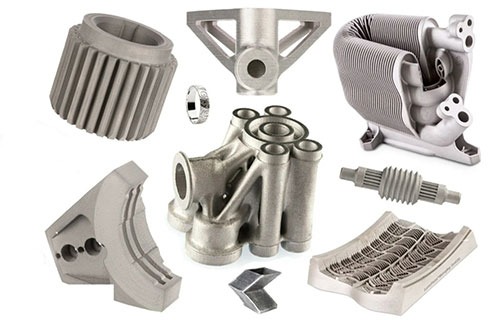
In the race to bring a new product to market, the prototyping phase is often the most critical bottleneck. You face the relentless pressure of time, budget, and the agonizing risk of discovering a fatal design flaw only after committing to expensive production tooling. Traditional prototyping methods like CNC machining or manual fabrication are slow, costly, and inherently limit design complexity.
Key takeaways
- In professional contexts, a “solid prototype” is more than a physical mock-up.
- The value proposition of 3D printing for solid prototyping is multi-dimensional, creating a compound advantage that is difficult to replicate with subtractive methods.
- Not all “solid” prototypes are equal. The optimal combination of technology and material is dictated by the prototype’s specific validation goal.
- Even with the right tools, mistakes happen. Here’s how to avoid the major ones:
What Truly Defines a “Solid Prototype” in 3D Printing?
In professional contexts, a “solid prototype” is more than a physical mock-up. It is a fully dense, dimensionally accurate, and functionally representative model created directly from digital data, layer by layer. Unlike hollow or shell-like models, solid prototypes are characterized by their structural integrity, enabling them to be used for rigorous fit, form, and functional testing. The “solid” nature can be achieved through high infill density in FDM printing, the inherently solid process of resin curing (SLA/DLP), or the sintered/fused nature of powder-based technologies (SLS, SLM). This key characteristic is what bridges the gap between a visual concept and a testable component.
What Are the Compounding Strategic Advantages Over Traditional Methods?
The value proposition of 3D printing for solid prototyping is multi-dimensional, creating a compound advantage that is difficult to replicate with subtractive methods.
- Radical Compression of the Iteration Loop: The most significant impact is on development speed. A design change that would require weeks to re-program and re-machine a metal or plastic block can be updated in the CAD model and reprinted in a matter of hours or days. A study by the Aberdeen Group found that companies using 3D printing for prototyping reduce their time-to-market by up to 50-70% compared to those using traditional methods. This allows for more iterations within the same timeframe, leading to a more refined and de-risked final product.
- Economic Viability for Low Volumes and Complex Designs: Traditional CNC machining or injection molding for prototypes incurs high non-recurring engineering (NRE) costs, primarily from custom tooling and fixture setup. 3D printing eliminates these costs entirely. The economics are simple: the cost of the first prototype is virtually the same as the tenth. This makes it perfectly suited for A/B testing variations, creating bespoke one-off tools, or producing small batches of pre-production units for user testing without the financial burden of tooling.
- Unleashing “Complexity for Free”: This is perhaps the most transformative benefit. In additive manufacturing, geometric complexity adds negligible cost. Internal lattices for lightweighting, conformal cooling channels, organic shapes, and consolidated assemblies that would be impossible or prohibitively expensive to machine become straightforward to print.
Case Study: The Consolidated Drone ChassisA robotics startup was developing an advanced drone. The initial design involved over 12 separate aluminum and plastic parts, requiring significant assembly and creating multiple potential failure points. Using Selective Laser Sintering (SLS) with nylon, they redesigned the entire central chassis and arm assembly into a single, monolithic “solid” prototype. This printed part integrated mounting points, cable routing channels, and vibration-dampening lattice structures. The result was a 40% reduction in part count, a 15% weight saving, and a drastic increase in structural rigidity. They were able to test this complete assembly in flight conditions after just 48 hours of printing, a feat impossible with their previous machined approach.
How Do You Select the Right Technology and Material for Your Prototype’s Purpose?
Not all “solid” prototypes are equal. The optimal combination of technology and material is dictated by the prototype’s specific validation goal.
| Prototype Goal (What are you testing?) | Recommended Technology | Ideal Material(s) | Why It’s the Best Fit |
|---|---|---|---|
| Form & Fit / Visual Presentation | SLA / DLP (Resin) | Standard, Tough, or ABS-Like Resins | Achieves near-injection-molded surface finish and fine detail, perfect for ergonomic reviews and stakeholder presentations. |
| Functional & Mechanical Testing | FDM / FFF | PETG, ABS, Nylon, PC (Polycarbonate) | Offers excellent strength-to-cost ratio. PETG is great for general durability; PC for high heat and impact; Nylon for toughness and fatigue resistance. |
| Complex, Load-Bearing & Snap-Fit Assemblies | SLS (Powder Bed Fusion) | Nylon 11, Nylon 12 (PA11/PA12) | Produces isotropically strong, durable parts with no support structures, ideal for testing intricate mechanisms and under-stress components. |
| High-Fidelity Thermal or Chemical Testing | Advanced FDM or SLS | PEI (ULTEM), PEEK, Chemical-Resistant Nylons | These high-performance engineering thermoplastics mimic the thermal and chemical resistance of final production materials for accurate environmental testing. |
| Metal Part Validation (Form, Fit, Light Load) | Binder Jetting or FDM with Metal Fill | Stainless Steel, Bronze (green state, sintered) | Provides a metal prototype at a fraction of the cost of full DMLS, suitable for checking fit with other metal components and basic functional checks. |
What Does a Professional Solid Prototyping Workflow Look Like?
Success requires a disciplined, end-to-end process.
- Define the Validation Objective: Start by asking, “What must this prototype prove?” Is it a dimensional fit check, a user feel test, or a failure point under load? This dictates every subsequent decision.
- Design for Additive Manufacturing (DfAM): Optimize the CAD model for the chosen 3D printing process. This includes: Orienting the part to maximize strength and minimize supports. Specifying critical tolerances (adding clearance for press-fits, accounting for shrinkage). Incorporating test features (like ribs or gussets) directly into the prototype design.
- Technology & Material Selection: Use the matrix above to make an informed choice.
- Print Preparation & Execution: This involves precise slicer configuration for infill, perimeters, and support strategy. For critical prototypes, print a small test coupon first to verify material properties and printer calibration.
- Post-Processing & Validation: Support removal, surface finishing (sanding, priming), and, crucially, measurement. Use calipers, CMM (Coordinate Measuring Machine), or 3D scanners to verify the prototype against the original CAD model. Document any deviations.
How to write a spec that gets priced correctly
A drawing is a contract. If it leaves a number open, the shop fills that number in with its own default. The default is rarely the one you had in mind. Put these five lines on every RFQ and most of the back-and-forth disappears before it starts.
- File format and units, with the model exported in millimetres
- Process and material grade, not a trade name
- Critical features and the tolerance each one needs
- Surface finish and the faces it applies to
- Quantity for the pilot build and for the year
The point is not paperwork. Each line removes a decision the shop would otherwise make for you. A complete RFQ comes back priced. An incomplete one comes back guessed.
What actually drives the price
Buyers usually push on material because it is the line they can see. In practice the material is rarely the biggest number on a quote. These five lines decide most of it:
- build volume and orientation
- layer height and support structure
- material grade and colour
- post-processing and hand finishing
- quantity per build plate
Ask for the quote split by line. A supplier who cannot break it down is guessing, and you will pay for the guess. The line you can usually renegotiate is the tolerance band, not the raw material.
Problems you will meet, and the fix
Every process has a failure mode it prefers. The same four show up again and again on this kind of work, and none of them are mysteries once you know what to look for.
- Warping on long flat faces where the part lifts off the plate
- Layer lines showing through a cosmetic surface
- Support scars on a mating face nobody flagged
- Dimensional drift on thin walls after cooling
Catch the fault on the first part, not the hundredth. A first-article check costs an hour. A bad batch costs the whole order. Write the check into the purchase order so nobody has to remember it.
What to check on the first article
The first article is the cheapest inspection you will ever buy. Use it properly and the rest of the run becomes boring, which is exactly what you want.
- Every dimension on the drawing, with the measured value written beside it.
- The material certificate, matched to the heat or lot number on the parts.
- The finish against the sample you approved, under the same light.
- Fit against the mating part, assembled rather than measured.
- Packaging, because parts that arrive damaged were never in tolerance.
Check in this order: datums, then mating features, then cosmetic faces. If the datums are wrong, every number after them is noise. Keep the report on file. When a problem shows up in month six, that document is the only thing that tells you what changed.
How to compare two quotes fairly
Two numbers are not comparable unless the scope matches. Line them up before you decide, because a low number with three gaps is not a low number.
Same drawing, same material, same finish, same inspection. Anything else is a different job wearing the same part number. Then look at what each quote leaves out. Freight, packaging, certificates and tooling are the usual gaps.
Ask each supplier to state their assumptions in writing. The one who does is usually the one who has run the process before.
Scaling from one part to a batch
The first part teaches you the process. The hundredth teaches you the process cost.
Watch three things as volume grows: setup amortisation, tool wear, and how much hand work the finish still needs. If the unit price barely moves between ten and a hundred, the cost sits in material or in hand work, not in setup. Ask which, because only one of them is negotiable.
Lead time behaves the same way. A one-off is scheduled around other jobs. A repeat order is scheduled around your forecast. Give the shop a forecast and the lead time gets shorter, not longer.
How to read a supplier's quote
A quote is a short document with a long shadow. Four things in it decide whether the job runs smoothly, and only one of them is the price.
- The scope line. It should name the process, the material and the finish, not just the part.
- The tolerance basis. General tolerance or the drawing, and which standard it follows.
- The exclusions. Tooling, freight, certificates and inspection are the usual omissions.
- The validity date. Material prices move, and an open-ended quote is a promise nobody can keep.
Read the exclusions before you read the total. A quote that leaves out tooling is not cheaper. It is a quote for a different job.
What Are the Common Pitfalls and How to Mitigate Them?
Even with the right tools, mistakes happen. Here’s how to avoid the major ones:
- Pitfall: Underestimating Material Behavior. Scenario: A PLA prototype passes a room-temperature fit test but fails miserably when installed in a sun-exposed enclosure. Mitigation: Always prototype with a material that matches or approximates the thermal and chemical environment of the final product. Use ABS or ASA for outdoor/automotive applications.
- Pitfall: Ignoring Anisotropy in FDM Prints. Scenario: A bracket printed in a strong material like PETG snaps because the load was applied perpendicular to the layer lines (the weakest direction). Mitigation: Orient the print so that the primary stress is applied parallel to the layer lines. For critical load-bearing parts, consider SLS technology, which offers more isotropic properties.
- Pitfall: Designing for Machining, Not for Additive. Scenario: Simply using a CNC-ready CAD file for 3D printing, resulting in excessive material use, long print times, and missed opportunities for consolidation. Mitigation: Embrace DfAM. Consolidate assemblies, hollow non-critical volumes with escape holes, and use lattices. This reduces weight, cost, and print time while often improving performance.
3D printing for solid prototypes is far more than a convenient way to make a physical model. It is a fundamentally different approach to product development that prioritizes speed, iteration, and the exploration of optimal design over the constraints of traditional manufacturing. By strategically matching the prototype’s purpose to the appropriate technology and material, and by adhering to a disciplined DfAM-oriented workflow, teams can unlock unprecedented agility. This allows them to fail fast and cheaply in the digital-to-physical transition, converge on superior designs more quickly, and ultimately bring better, more innovative products to market with greater confidence and significantly reduced risk. The solid prototype is no longer just a step in the process—it is the physical embodiment of a faster, smarter, and more creative path to production.
FAQ (Frequently Asked Questions)
Q: Can a 3D printed solid prototype be as strong as an injection-molded or machined part?
A: It depends on the technology and material, but it can come very close or even match it in specific scenarios. SLS Nylon parts have excellent and isotropic mechanical properties, often suitable as end-use parts. High-performance FDM materials like PC or PEI can surpass the strength of common plastics like ABS. However, 3D printed parts have a different internal structure (layer adhesion) compared to homogeneous molded parts. For direct comparison, the prototype should be printed in an orientation that maximizes strength for the intended load and with the appropriate infill (often 80-100% for solid simulation).
Q: How do I accurately estimate the cost and time for a solid prototype?
A: Use your slicer software as a costing engine. After preparing the print, the slicer will provide an estimate of material volume/weight and print time. Multiply the material weight by its cost per kilogram, and add a factor for machine time (if applicable) and post-processing labor. For time, add 10-20% contingency to the slicer’s estimate for setup, potential pauses, and post-processing. For quick quotes from service bureaus, provide the 3D file, desired material, and quantity.
Q: What is the largest single-piece solid prototype I can reasonably 3D print?
A: For in-house printing, it’s limited by your machine’s build volume (typically up to 300x300x400mm for desktop industrial). For larger prototypes, the standard practice is segmentation. The part is intelligently split into sections with alignment features (dowels, interlocking joints), printed separately, and then assembled using high-strength adhesives or mechanical fasteners. This is common for automotive dashboards, large-scale architectural models, or full-size furniture prototypes.
Q: When does it still make sense to use CNC machining over 3D printing for a solid prototype?
A: CNC is preferable when: 1) You need the exact final material (e.g., a specific grade of aluminum) for testing, 2) The part has simple, primarily orthogonal geometries that are faster/cheaper to machine, 3) You require ultra-high surface finish or tight tolerances on all faces that would require excessive post-processing on a 3D print, or 4) You are producing a larger batch (e.g., 50+ units) where the upfront CNC programming cost is amortized effectively. The decision is often economic and geometric.
Our solution for 3D Printing Solid Prototypes Revolutionize
YiguProto runs 3D printing in house, from a single prototype to a production batch. We quote the process, the material and the finish as separate lines, so you can see where the money goes instead of arguing with one number.
Send a STEP file or a drawing and you get a DFM report in one to two business days. It flags the features that add cost and the features that will not hold tolerance on the process you picked.
Every order ships with an inspection report on the features you call out. If a part misses, we make it again. Ready to price a part? Start with a free quote and DFM review, or read more about our 3D printing. You can also talk to an engineer before you commit to a drawing.
FAQ about 3D Printing Solid Prototypes Revolutionize
How do I compare two quotes fairly?
Match the scope first: same drawing, same material, same finish, same inspection. Then read the exclusions. Freight, tooling and certificates are the usual gaps, and a low number with three gaps is not a low number.
What should I check before approving the parts?
Datums first, then the features that mate, then the cosmetic faces. Ask for a dimensional report, a material certificate and a finish sample. A part can be inside every tolerance and still not fit, so assemble one before you sign.
How much does 3D Printing Solid Prototypes Revolutionize cost?
Price comes from five lines: material, machine or tool time, setup, finishing and inspection. The material itself is usually the smallest of them. Send a drawing and we will split the quote so you can see which line is doing the damage.
What is 3D Printing Solid Prototypes Revolutionize used for?
3D Printing Solid Prototypes Revolutionize turns up wherever the part has to do a real job at a predictable cost: brackets, housings, fixtures, covers and the fittings that hold them together. The honest test is whether the properties match the load and the environment, not whether the material is fashionable.
How long does a first article take?
Usually a few business days once the drawing is frozen, and longer if tooling is involved. The date we give you is the date we confirm in writing, not the date we hope for.
Does the process work for prototypes as well as production?
Yes, and that is usually the point. Running the prototype on the production process removes a whole class of surprises, because the part you test is made the same way as the part you sell.
The short version
3D Printing Solid Prototypes Revolutionize rewards the buyer who reads the data sheet and the drawing together. Pick the option for the property that matters, not for the price per kilo.
Tighten only what mates. Test a sample before the run. Then let the process do the rest.