
3D Printing
Need a Clear 3D Printed Part? How to Choose Right Transparent Material
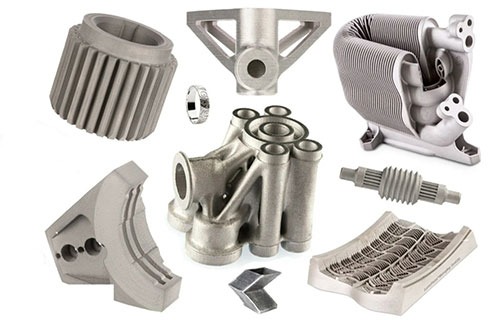
Creating truly transparent 3D printed parts requires a strategic combination of specialized materials, precision printing processes, and meticulous post-processing to achieve optical clarity and functional performance. Unlike opaque prints, transparent parts demand careful attention to internal light scattering, layer lines, and surface finish.
Key takeaways
- The promise of 3D printing a perfectly transparent lens, a medical fluidic device, or a sleek architectural model is compelling, yet the reality is often a translucent or hazy part.
- Not all 3D printing processes are created equal for clarity. The technology choice dictates the starting point for achievable quality.
- Each material family offers a different balance of clarity, mechanical properties, and ease of use.
- The print is only half the battle. Post-processing is essential to unlock transparency.
Introduction: The Challenge of Clarity in Additive Manufacturing
The promise of 3D printing a perfectly transparent lens, a medical fluidic device, or a sleek architectural model is compelling, yet the reality is often a translucent or hazy part. Achieving genuine transparency is one of the most demanding challenges in additive manufacturing. It requires navigating a complex interplay of material science, optical physics, and process engineering. Success hinges on understanding that transparency is not an inherent property of a material alone, but the final result of a meticulously controlled workflow designed to minimize light diffusion. This guide demystifies that workflow, helping you solve the unique challenges of 3D printing clear parts for applications in prototyping, medical devices, lighting, and consumer products.
What Defines “Transparency” in 3D Printing?
Before selecting a material, it’s crucial to define the goal. “Transparent” in 3D printing exists on a spectrum, often measured by light transmittance percentage and haze.
- Optical Clarity vs. Diffusion: True optical clarity, like a window, allows undistorted vision. This is extremely difficult with layer-based processes. More commonly, 3D prints achieve translucency or diffused transparency, where light passes through but details are blurred—ideal for light guides or covers where hiding internal components is desirable.
- Key Disruptors of Clarity: The primary enemies are layer lines (causing diffraction), micro-bubbles or porosity within the material, internal stress creating birefringence (visible color patterns under polarized light), and surface roughness. The chosen technology and post-process must combat these.
Which 3D Printing Technologies Can Produce Transparent Parts?
Not all 3D printing processes are created equal for clarity. The technology choice dictates the starting point for achievable quality.
- Vat Photopolymerization (SLA, DLP): The current gold standard for high-detail transparency. These processes cure liquid resin with a laser or projector, producing parts with inherently smooth surfaces and excellent homogeneity when using clear resins. They offer the best potential for near-optical clarity after post-processing.
- Material Extrusion (FDM/FFF): The most accessible but most challenging method for clarity. The extruded thermoplastic filament creates pronounced layer lines and internal air gaps. Achieving transparency requires specific materials and intensive post-processing to “weld” the layers together optically.
- Material Jetting (PolyJet): A high-end process that jets and UV-cures droplets of photopolymer. It can produce very smooth, clear parts and is unique in its ability to print multiple materials simultaneously, such as transparent and opaque or flexible materials in a single build.
- Powder Bed Fusion (SLS, MJF): Generally unsuitable for transparent parts, as the sintered powder inherently creates a porous, light-scattering structure, resulting in opaque or grainy finishes.
What Are the Leading Transparent Material Options?
Each material family offers a different balance of clarity, mechanical properties, and ease of use.
1. Transparent Photopolymer Resins (for SLA/DLP)
These are the most straightforward path to clarity.
- Standard Clear Resins: Offer good initial clarity (85-90%+ light transmission) and are easy to print. However, they can yellow over time with UV exposure and are typically more brittle than engineering resins.
- Tough or Durable Clear Resins: Formulations like Formlabs Clear Resin or Dental SG offer improved impact resistance and reduced brittleness while maintaining good clarity. They are often designed for functional prototyping and medical applications.
- High-Temperature Clear Resins: For applications requiring thermal stability, these resins can have Heat Deflection Temperatures (HDT) exceeding 200°C, making them suitable for fluidic channels or light housings.
- Pro-Tip: Always review the manufacturer’s post-curing instructions. Undercuring leaves parts sticky and weak; over-curing can induce yellowing and brittleness.
2. Transparent Thermoplastics (for FDM/FFF)
These require more skill but offer superior mechanical and thermal properties.
- Polycarbonate (PC): The strongest transparent FDM material. It offers high impact resistance, excellent heat resistance (HDT ~110°C), and good clarity potential. However, it is highly hygroscopic (absorbs moisture) and prone to warping, demanding a sealed drybox and an enclosed, heated printer chamber.
- PETG (Glycol-modified PET): The most user-friendly transparent filament. It prints more easily than PC, has good layer adhesion, and is naturally clearer straight off the printer. Its clarity and chemical resistance make it popular for prototypes, display items, and light-duty functional parts.
- Acrylic (PMMA) & ASA: Specialized transparent variants exist. PMMA offers the highest potential clarity (glass-like) but is notoriously difficult to print due to high warping and tendency to bubble. ASA offers UV stability for outdoor applications.
3. Advanced & Specialized Options
- Clear Polypropylene (PP): For applications requiring chemical resistance and living hinges, transparent PP filaments are emerging.
- Transparent Composites (e.g., Clear PC with Glass Beads): These are engineered to have a matched refractive index between the polymer matrix and the filler, reducing light scattering at their interface to improve clarity in thicker sections.
Comparison Guide: Transparent Material Selection
| Material | Best Technology | Key Strengths | Key Challenges | Ideal Application |
|---|---|---|---|---|
| Standard Clear Resin | SLA, DLP | Highest potential clarity, smooth surface, fine detail. | Brittle, can yellow, limited thermal/chemical resistance. | Visual prototypes, display models, art pieces. |
| Tough/Durable Clear Resin | SLA, DLP | Good clarity with improved impact resistance, often biocompatible. | More expensive than standard resin. | Functional prototypes, medical device housings, fluidic channels. |
| PETG | FDM/FFF | Good balance of clarity, strength, and printability, chemical resistant. | Can be stringy; inherent layer lines reduce clarity. | Prototype enclosures, light diffusers, containers. |
| Polycarbonate (PC) | FDM/FFF | Exceptional strength and heat resistance, good clarity potential. | Very difficult to print (warping, moisture), requires high temps. | High-stress transparent parts, protective covers, engineering prototypes. |
| Multi-Material (VeroClear + Rubber) | PolyJet | Complex assemblies in one print, very smooth finish. | Very high machine cost, parts can be fragile. | Prototypes with integrated seals/gaskets, complex lenses. |
What Is the Critical Post-Processing Workflow for Maximum Clarity?
The print is only half the battle. Post-processing is essential to unlock transparency.
For Resin Parts:
- Thorough Washing: Residual uncured resin on the surface will cure into a cloudy film. Use a two-stage wash in 99% isopropyl alcohol (IPA).
- Proper UV Curing: Cure according to the resin’s datasheet. A rotating turntable in a UV curing chamber ensures even exposure and complete polymerization.
- Sanding and Polishing: This is the key to removing layer lines. Start with wet sanding using progressively finer grits (400 -> 800 -> 1000 -> 1500 -> 2000+ grit). Follow with a plastic polishing compound (like Novus or Meguiar’s) applied with a soft cloth or buffing wheel.
- Clear Coating (Optional): Applying a thin, clear acrylic or epoxy spray coat can fill microscopic scratches and restore a uniform glossy finish.
For FDM Parts (The “Epoxy Method”):
Achieving glass-like clarity with FDM is an advanced technique:
- Print with 100% Infill: Use a rectilinear or gyroid pattern to minimize internal voids. Increase extrusion multiplier slightly to ensure no gaps.
- Smooth the Surface: Lightly sand to reduce major layer lines.
- Apply a Clear Epoxy Resin Coat: The core technique is to brush or pour a low-viscosity, UV-stable epoxy resin (used for tabletops) over the part. The epoxy fills the layer lines and air gaps, creating a smooth, transparent outer shell as it cures. Multiple thin coats are better than one thick coat.
- Sand and Polish the Cured Epoxy: Once fully cured, sand the epoxy coating with ultra-fine grits and polish to a high gloss.
How to write a spec that gets priced correctly
A drawing is a contract. If it leaves a number open, the shop fills that number in with its own default. The default is rarely the one you had in mind. Put these five lines on every RFQ and most of the back-and-forth disappears before it starts.
- File format and units, with the model exported in millimetres
- Process and material grade, not a trade name
- Critical features and the tolerance each one needs
- Surface finish and the faces it applies to
- Quantity for the pilot build and for the year
The point is not paperwork. Each line removes a decision the shop would otherwise make for you. A complete RFQ comes back priced. An incomplete one comes back guessed.
What actually drives the price
Buyers usually push on material because it is the line they can see. In practice the material is rarely the biggest number on a quote. These five lines decide most of it:
- build volume and orientation
- layer height and support structure
- material grade and colour
- post-processing and hand finishing
- quantity per build plate
Ask for the quote split by line. A supplier who cannot break it down is guessing, and you will pay for the guess. The line you can usually renegotiate is the tolerance band, not the raw material.
Problems you will meet, and the fix
Every process has a failure mode it prefers. The same four show up again and again on this kind of work, and none of them are mysteries once you know what to look for.
- Warping on long flat faces where the part lifts off the plate
- Layer lines showing through a cosmetic surface
- Support scars on a mating face nobody flagged
- Dimensional drift on thin walls after cooling
Catch the fault on the first part, not the hundredth. A first-article check costs an hour. A bad batch costs the whole order. Write the check into the purchase order so nobody has to remember it.
What to check on the first article
The first article is the cheapest inspection you will ever buy. Use it properly and the rest of the run becomes boring, which is exactly what you want.
- Every dimension on the drawing, with the measured value written beside it.
- The material certificate, matched to the heat or lot number on the parts.
- The finish against the sample you approved, under the same light.
- Fit against the mating part, assembled rather than measured.
- Packaging, because parts that arrive damaged were never in tolerance.
Check in this order: datums, then mating features, then cosmetic faces. If the datums are wrong, every number after them is noise. Keep the report on file. When a problem shows up in month six, that document is the only thing that tells you what changed.
How to compare two quotes fairly
Two numbers are not comparable unless the scope matches. Line them up before you decide, because a low number with three gaps is not a low number.
Same drawing, same material, same finish, same inspection. Anything else is a different job wearing the same part number. Then look at what each quote leaves out. Freight, packaging, certificates and tooling are the usual gaps.
Ask each supplier to state their assumptions in writing. The one who does is usually the one who has run the process before.
Scaling from one part to a batch
The first part teaches you the process. The hundredth teaches you the process cost.
Watch three things as volume grows: setup amortisation, tool wear, and how much hand work the finish still needs. If the unit price barely moves between ten and a hundred, the cost sits in material or in hand work, not in setup. Ask which, because only one of them is negotiable.
Lead time behaves the same way. A one-off is scheduled around other jobs. A repeat order is scheduled around your forecast. Give the shop a forecast and the lead time gets shorter, not longer.
How to read a supplier's quote
A quote is a short document with a long shadow. Four things in it decide whether the job runs smoothly, and only one of them is the price.
- The scope line. It should name the process, the material and the finish, not just the part.
- The tolerance basis. General tolerance or the drawing, and which standard it follows.
- The exclusions. Tooling, freight, certificates and inspection are the usual omissions.
- The validity date. Material prices move, and an open-ended quote is a promise nobody can keep.
Read the exclusions before you read the total. A quote that leaves out tooling is not cheaper. It is a quote for a different job.
What to send with the first order
The first order sets the pattern for every order after it. Send a complete package once and the shop files it, and the second order takes a fraction of the time.
- A STEP or native model plus a PDF drawing carrying the same revision letter.
- The material callout by standard number, not by trade name.
- The finish and the exact faces it applies to.
- Any test the part must pass: fit, seal, drop, salt spray, dielectric.
- A contact who can answer a question inside one working day.
Then write down what was agreed. An email that confirms the material, the finish and the date is worth more than a longer purchase order that leaves them open.
When this is the wrong choice
A good supplier tells you when the process does not fit. These are the cases where we say so.
- The volume is so low that setup costs more than the parts are worth.
- The tolerance is tighter than the process can hold without a second operation.
- The geometry cannot be made without a tool feature that will not pay back.
- The material you need is not available in the form the process requires.
- The schedule is shorter than the tooling or setup time, and nobody has said so yet.
None of these are refusals. They are reasons to look at a different route, and the earlier that conversation happens the cheaper it is. The most expensive mistake in manufacturing is a process chosen before the question was understood.
Conclusion: A Clear Path Forward
3D printing transparent parts is a demanding but solvable engineering challenge. The path to success is systematic: begin by defining the required level of optical clarity and functional performance, then select the most appropriate technology and material combination. For most users seeking the best clarity with the least hassle, SLA/DLP with a high-quality clear resin and diligent post-processing is the recommended route. For applications requiring the ultimate toughness and heat resistance, FDM with polycarbonate and advanced epoxy finishing presents a viable, though more complex, alternative. By understanding the science behind light transmission and dedicating time to surface finishing, you can reliably produce clear, high-quality parts that meet both aesthetic and functional demands.
How we can help
YiguProto runs 3D printing in house, from a single prototype to a production batch. We quote the process, the material and the finish as separate lines, so you can see where the money goes instead of arguing with one number.
Send a STEP file or a drawing and you get a DFM report in one to two business days. It flags the features that add cost and the features that will not hold tolerance on the process you picked.
Every order ships with an inspection report on the features you call out. If a part misses, we make it again. Ready to price a part? Start with a free quote and DFM review, or read more about our 3D printing. You can also talk to an engineer before you commit to a drawing.
Frequently asked questions
What should I check before approving the parts?
Datums first, then the features that mate, then the cosmetic faces. Ask for a dimensional report, a material certificate and a finish sample. A part can be inside every tolerance and still not fit, so assemble one before you sign.
How do I compare two quotes fairly?
Match the scope first: same drawing, same material, same finish, same inspection. Then read the exclusions. Freight, tooling and certificates are the usual gaps, and a low number with three gaps is not a low number.
What happens if a part is out of specification?
We measure it against the same drawing you approved and, if it misses, we make it again. What matters is that the report exists, because a disagreement without data is just an opinion.
Does the process work for prototypes as well as production?
Yes, and that is usually the point. Running the prototype on the production process removes a whole class of surprises, because the part you test is made the same way as the part you sell.
Is there a minimum order quantity?
No hard minimum. One part is fine. What changes with volume is which costs dominate, so a single unit is priced mostly on setup and a thousand units are priced mostly on cycle time and material.
What files do you need in order to quote?
A STEP file plus a PDF drawing that carries the same revision letter. The model carries the geometry and the drawing carries the intent. When the two disagree, the shop picks one, and it is never the one you meant.
The short version
Good parts reward the buyer who reads the data sheet and the drawing together. Pick the option for the property that matters, not for the price per kilo.
Tighten only what mates. Test a sample before the run. Then let the process do the rest.