
3D Printing
How Accurate Can Metal 3D Printing Really Be?
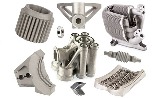
The accuracy of metal 3D printing, often cited as a key advantage, is not a single, guaranteed number but a multifaceted outcome influenced by technology, process, and design. While manufacturers may advertise theoretical tolerances as tight as ±0.01mm, real-world production accuracy is typically in the range of ±0.05mm to ±0.2mm per 100mm of build, with surface roughness between 4-15 micrometers (Ra).
Key takeaways
- Understanding accuracy starts with separating theoretical resolution from achievable tolerances in production.
- High accuracy is achieved through precise control of energy, material, and heat.
- Even with precise machines, inherent physical phenomena introduce deviations. The dominant challenge is managing thermal stress.
- Achieving accuracy is as much about Design for Additive Manufacturing (DfAM) as it is about machine operation.
What Are the Realistic Accuracy Benchmarks?
Understanding accuracy starts with separating theoretical resolution from achievable tolerances in production. The former is about the printer’s finest possible feature; the latter is about reliably hitting a target dimension after all processing is complete.
The following table compares the practical accuracy outcomes of the two dominant metal AM processes:
| Accuracy Metric | Laser Powder Bed Fusion (LPBF/DMLS) | Binder Jetting (BJ) | Key Influencing Factor |
|---|---|---|---|
| Dimensional Tolerance (per 100mm) | ±0.05mm to ±0.2mm | ±0.1mm to ±0.3mm | LPBF: Thermal stress & shrinkage. BJ: Sintering shrinkage & powder packing. |
| Surface Roughness (Ra) | 10 – 25 µm (as-printed) | 5 – 15 µm (as-printed, post-sintered) | LPBF: Stair-step effect & partially melted powder. BJ: Powder particle size. |
| Minimum Feature Size | 0.2 – 0.5 mm (walls, channels) | 0.5 – 1.0 mm | LPBF: Laser spot size (~70-100µm). BJ: Binder droplet size & powder flow. |
| Key Post-Process | Stress relief, Hot Isostatic Pressing (HIP), machining. | Debinding & Sintering (15-20% linear shrinkage). | BJ shrinkage is predictable but must be pre-compensated in the CAD model. |
Interpreting the Data:
An aerospace manufacturer printing a titanium satellite bracket with LPBF can reliably expect features to be within ±0.1mm of the design. However, the “as-printed” surface will be rough, like fine-grit sandpaper (~15µm Ra). For a bearing surface, they will need to machine it, adding a machining allowance to the original design. In contrast, a dental lab using Binder Jetting for cobalt-chromium crowns gets a smoother surface off the printer but must design the part ~20% larger to account for predictable shrinkage during the furnace sintering stage.
What Drives Accuracy in Metal AM?
High accuracy is achieved through precise control of energy, material, and heat.
- Precision Energy Delivery: In LPBF, a focused laser with a spot size as small as 70 microns scans across the powder bed. The system’s galvanometers position this laser with extreme speed and precision. The key is consistent melt pool dynamics—ensuring each tiny weld pool is the same size and depth. Fluctuations in laser power or scan speed create inconsistencies that ripple through the part.
- Layerwise Control and Monitoring: Each layer of powder, typically 20-60 microns thick, is spread by a recoater blade with micron-level flatness. Advanced systems use in-situ process monitoring—high-speed cameras and thermal sensors—to detect anomalies like spatter or lack-of-fusion in real-time. This allows for layer-by-layer validation, a form of digital quality assurance.
- The Additive Advantage Over Subtractive: Unlike machining, which can induce stress and vibration in a part, AM builds geometry without external force. This allows for the creation of internal channels, conformal cooling paths, and lattice structures that are impossible to machine accurately. The absence of cutting tool deflection is a fundamental accuracy benefit for complex parts.
Case Study: Conformal Cooling in Injection Molds:
A mold maker needed cooling channels that followed the curved surface of a plastic part to reduce cycle time. Milling straight drill lines would be inaccurate and inefficient. Using LPBF, they printed the mold insert with snaking cooling channels just 3mm in diameter, placed 2mm from the mold surface with perfect conformity. The accuracy of the channel placement, within ±0.1mm of the CAD model, was unachievable with traditional methods and led to a 30% reduction in cooling time.
What Are the Primary Causes of Inaccuracy?
Even with precise machines, inherent physical phenomena introduce deviations. The dominant challenge is managing thermal stress.
1. Thermal Distortion and Residual Stress:
As the laser melts and cools metal rapidly, localized heating and cooling create huge thermal gradients. This causes material to expand and contract unevenly, leading to:
- Warping: The part pulls away from the build plate or distorts, like a potato chip. This is most severe with large, flat features.
- Delamination: Layers crack and separate due to internal stress.
- Support Structure Failure: Stresses can crack support structures, causing build failures.
Mitigation Strategy: This is tackled through intelligent design and process parameters. Adding strategic supports acts as anchors to resist warping. Using pre-heated build plates (up to 200°C for some alloys) reduces the temperature gradient. A laser scan strategy that rotates scan direction between layers also helps distribute stress.
2. Powder-Based Inaccuracies:
- Particle Size and Recoating: Irregular powder or a poorly tuned recoater can create an uneven powder bed. A thin spot results in a lack of fusion (“porosity”); a thick spot can cause a dimensional bump.
- Part Curl and “Dross”: At the edges of a part, heat can bleed into the surrounding powder, causing slight sintering. This creates a rough, dimensional inaccuracy known as dross or “edge effect.”
3. Post-Processing Dimensional Shifts:
- Stress Relief & HIP: The heat treatment used to relieve internal stress can cause slight, unpredictable dimensional shifts.
- Support Removal and Machining: The manual or EDM removal of supports can nick the part surface. Any subsequent CNC machining for precision features must be planned for, adding cost and time.
How Can You Design for Maximum Accuracy?
Achieving accuracy is as much about Design for Additive Manufacturing (DfAM) as it is about machine operation.
- Strategic Orientation: Part orientation on the build plate is the single most important DfAM decision for accuracy. Orient critical features and mating surfaces vertically or at a steep angle. This minimizes the stair-step effect and produces a better surface finish on those faces. Avoid large, flat surfaces parallel to the build plate, as they are prone to warping.
- Intelligent Support Design: Supports are necessary but damage surfaces. Use block supports for strong anchoring in high-stress areas and pin or tree supports for better surface finish on less critical faces. Design breakpoints into supports for easier removal.
- Incorporate Anticipated Distortion: For some high-precision applications, advanced shops use compensated CAD models. By printing test artifacts, they measure actual distortion patterns and then pre-distort the original CAD file in the opposite direction, so the printed part “warps” into the correct shape. This is common in large-format metal AM for aerospace.
- Include Machining Allowances: For any feature requiring a tolerance tighter than ±0.05mm or a surface finish smoother than 4µm Ra, you must design an excess of material—a machining allowance—to be removed via post-print CNC machining. A typical allowance is 0.2-0.5mm per surface.
How to write a spec that gets priced correctly
A drawing is a contract. If it leaves a number open, the shop fills that number in with its own default. The default is rarely the one you had in mind. Put these five lines on every RFQ and most of the back-and-forth disappears before it starts.
- File format and units, with the model exported in millimetres
- Process and material grade, not a trade name
- Critical features and the tolerance each one needs
- Surface finish and the faces it applies to
- Quantity for the pilot build and for the year
The point is not paperwork. Each line removes a decision the shop would otherwise make for you. A complete RFQ comes back priced. An incomplete one comes back guessed.
What actually drives the price
Buyers usually push on material because it is the line they can see. In practice the material is rarely the biggest number on a quote. These five lines decide most of it:
- build volume and orientation
- layer height and support structure
- material grade and colour
- post-processing and hand finishing
- quantity per build plate
Ask for the quote split by line. A supplier who cannot break it down is guessing, and you will pay for the guess. The line you can usually renegotiate is the tolerance band, not the raw material.
Problems you will meet, and the fix
Every process has a failure mode it prefers. The same four show up again and again on this kind of work, and none of them are mysteries once you know what to look for.
- Warping on long flat faces where the part lifts off the plate
- Layer lines showing through a cosmetic surface
- Support scars on a mating face nobody flagged
- Dimensional drift on thin walls after cooling
Catch the fault on the first part, not the hundredth. A first-article check costs an hour. A bad batch costs the whole order. Write the check into the purchase order so nobody has to remember it.
What to check on the first article
The first article is the cheapest inspection you will ever buy. Use it properly and the rest of the run becomes boring, which is exactly what you want.
- Every dimension on the drawing, with the measured value written beside it.
- The material certificate, matched to the heat or lot number on the parts.
- The finish against the sample you approved, under the same light.
- Fit against the mating part, assembled rather than measured.
- Packaging, because parts that arrive damaged were never in tolerance.
Check in this order: datums, then mating features, then cosmetic faces. If the datums are wrong, every number after them is noise. Keep the report on file. When a problem shows up in month six, that document is the only thing that tells you what changed.
How to compare two quotes fairly
Two numbers are not comparable unless the scope matches. Line them up before you decide, because a low number with three gaps is not a low number.
Same drawing, same material, same finish, same inspection. Anything else is a different job wearing the same part number. Then look at what each quote leaves out. Freight, packaging, certificates and tooling are the usual gaps.
Ask each supplier to state their assumptions in writing. The one who does is usually the one who has run the process before.
Scaling from one part to a batch
The first part teaches you the process. The hundredth teaches you the process cost.
Watch three things as volume grows: setup amortisation, tool wear, and how much hand work the finish still needs. If the unit price barely moves between ten and a hundred, the cost sits in material or in hand work, not in setup. Ask which, because only one of them is negotiable.
Lead time behaves the same way. A one-off is scheduled around other jobs. A repeat order is scheduled around your forecast. Give the shop a forecast and the lead time gets shorter, not longer.
How to read a supplier's quote
A quote is a short document with a long shadow. Four things in it decide whether the job runs smoothly, and only one of them is the price.
- The scope line. It should name the process, the material and the finish, not just the part.
- The tolerance basis. General tolerance or the drawing, and which standard it follows.
- The exclusions. Tooling, freight, certificates and inspection are the usual omissions.
- The validity date. Material prices move, and an open-ended quote is a promise nobody can keep.
Read the exclusions before you read the total. A quote that leaves out tooling is not cheaper. It is a quote for a different job.
What to send with the first order
The first order sets the pattern for every order after it. Send a complete package once and the shop files it, and the second order takes a fraction of the time.
- A STEP or native model plus a PDF drawing carrying the same revision letter.
- The material callout by standard number, not by trade name.
- The finish and the exact faces it applies to.
- Any test the part must pass: fit, seal, drop, salt spray, dielectric.
- A contact who can answer a question inside one working day.
Then write down what was agreed. An email that confirms the material, the finish and the date is worth more than a longer purchase order that leaves them open.
Where Does Accuracy Matter Most?
The value of metal AM accuracy is realized in fields where performance trumps all else.
- Aerospace & Defense: Here, accuracy is synonymous with performance and safety. Fuel nozzles with intricate internal channels must be printed to exact dimensions to ensure proper fuel-air mixing. A study by GE Aviation on their LEAP engine nozzles showed that AM’s accuracy enabled a single-piece design that was 25% lighter and five times more durable than the traditionally assembled predecessor, with no leakage paths.
- Medical & Dental Implants: This is the frontier of biomechanical accuracy. A titanium spinal fusion cage must have a specific pore size (e.g., 600±50 microns) to promote bone ingrowth, while the overall shape must match the patient’s anatomy from a CT scan within 0.1-0.2mm. AM is the only method that can achieve this geometric and porous complexity simultaneously.
- High-Performance Tooling & Automotive: Conformal cooling channels in molds and dies, as mentioned, rely on AM’s accuracy to place coolant optimally. In motorsports, complex topology-optimized suspension parts are printed to save weight while maintaining strength, with dimensional accuracy ensuring proper assembly and alignment under extreme loads.
The accuracy of metal 3D printing is a powerful but nuanced capability. It is not a fixed promise but a manageable outcome that sits at the intersection of advanced machine technology, deep material understanding, and intelligent design. By moving beyond vendor specifications to grasp the real-world benchmarks of ±0.05-0.2mm tolerance, by respecting the dominant role of thermal management and DfAM principles, and by planning for essential post-processing, engineers can harness this technology with confidence. In doing so, they unlock the ability to manufacture parts with a combination of complexity, lightweight design, and precision that is redefining what is possible in the most demanding industries on Earth—and beyond.
How we can help
YiguProto runs 3D printing in house, from a single prototype to a production batch. We quote the process, the material and the finish as separate lines, so you can see where the money goes instead of arguing with one number.
Send a STEP file or a drawing and you get a DFM report in one to two business days. It flags the features that add cost and the features that will not hold tolerance on the process you picked.
Every order ships with an inspection report on the features you call out. If a part misses, we make it again. Ready to price a part? Start with a free quote and DFM review, or read more about our 3D printing. You can also talk to an engineer before you commit to a drawing.
Frequently asked questions
What files do you need in order to quote?
A STEP file plus a PDF drawing that carries the same revision letter. The model carries the geometry and the drawing carries the intent. When the two disagree, the shop picks one, and it is never the one you meant.
How do I compare two quotes fairly?
Match the scope first: same drawing, same material, same finish, same inspection. Then read the exclusions. Freight, tooling and certificates are the usual gaps, and a low number with three gaps is not a low number.
Does the process work for prototypes as well as production?
Yes, and that is usually the point. Running the prototype on the production process removes a whole class of surprises, because the part you test is made the same way as the part you sell.
What happens if a part is out of specification?
We measure it against the same drawing you approved and, if it misses, we make it again. What matters is that the report exists, because a disagreement without data is just an opinion.
How long does a first article take?
Usually a few business days once the drawing is frozen, and longer if tooling is involved. The date we give you is the date we confirm in writing, not the date we hope for.
Is there a minimum order quantity?
No hard minimum. One part is fine. What changes with volume is which costs dominate, so a single unit is priced mostly on setup and a thousand units are priced mostly on cycle time and material.
The short version
Good parts reward the buyer who reads the data sheet and the drawing together. Pick the option for the property that matters, not for the price per kilo.
Tighten only what mates. Test a sample before the run. Then let the process do the rest.