
3D Printing
How Can 3D Printing Speed Up Robotics Development in 2026?
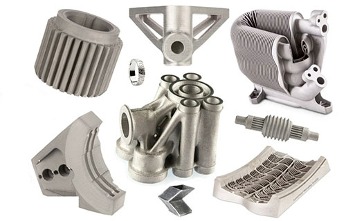
For robotics engineers and product managers, the race to innovate is faster than ever. The need to quickly test, refine, and deploy robotic solutions creates immense pressure. Traditional manufacturing often acts as a brake on this process, with long lead times and high costs for custom parts. This guide explores how 3D printing for robotics is solving these core challenges.
Key takeaways
- Robots are complex systems with many custom parts. These parts often have intricate geometries for sensors, wiring, and movement.
- Not all robot parts are the same. A cover needs a smooth finish. A joint needs to be tough. A gripper might need to be soft.
- You may need 10 or 50 custom robots for a pilot line or a special job. Traditional injection molding requires a high upfront cost for molds.
- A common worry is that 3D printed parts look amateurish. With proper post-processing, they can look and feel like mass-produced parts.
Why Use 3D Printing for Robots?
Robots are complex systems with many custom parts. These parts often have intricate geometries for sensors, wiring, and movement. Making these parts with CNC machining or injection molding is slow and expensive. It requires special tooling for each design change. This process kills innovation speed. 3D printing, or additive manufacturing, builds parts layer by layer from a digital file. It needs no custom tools. This fundamental difference unlocks new possibilities. It allows for rapid design cycles, complex shapes, and on-demand production. For robotics, this means you can test ideas faster and take more risks. You can create parts that were once impossible to make.
Speed Up Design Cycles?
Functional prototyping is the heart of robot development. You must test how parts move, fit, and bear load. Waiting for parts is the biggest delay. 3D printing slashes this wait time. A robot arm bracket that takes four weeks via CNC can be printed in two days. This speed allows for more iterations. You can test more design ideas in the same time frame. This leads to a better, more reliable final product.
A clear example comes from Universal Robots. In 2024, they developed a new adaptive gripper. Using traditional methods, each prototype took four weeks. They switched to FDM 3D printing with strong nylon. The prototype cycle dropped to just five days. This 80% reduction in time let them test ten different grip designs in two months. They found the optimal design faster. Physical testing also caught a fit and alignment issue not seen in simulation. Fixing it early saved thousands in later-stage rework. This is the power of speed.
Table: Traditional vs. 3D Printing Prototyping
| Aspect | Traditional Prototyping (CNC) | 3D Printing Prototyping |
|---|---|---|
| Lead Time | 4–6 weeks | 1–5 days |
| Cost per Part | $500 – $2,000+ | $50 – $500 |
| Design Change Cost | High (new tooling) | Low (CAD file edit) |
| Complex Shape Ability | Limited | Excellent |
Make Impossible Parts?
Robots need smart, efficient structures. Think of a robotic arm with internal channels for wires and air lines. Or a sensor housing with built-in mounts. Traditional manufacturing struggles with these single, complex parts. It would require making many pieces and assembling them. 3D printing excels here. It can create hollow structures, internal lattices, and organic shapes in one piece. This leads to parts that are lighter, stronger, and have fewer points of failure.
Boston Dynamics used this to its advantage for the Spot® robot. They needed a housing for a complex sensor array. It required many small cavities for wires. Using SLA 3D printing, they made it as one complete part. Traditional methods would need five separate parts and assembly. The printed housing cut part count and assembly time by 40%. It also improved reliability by removing screws and joints.
In agriculture, FarmBot used 3D printing in 2024. They made a plant-sensing arm. The design had a hollow core for water flow and soft, curved edges to protect plants. Molding this would be costly and need multiple parts. 3D printing made it a single, lightweight component. It reduced the arm’s weight by 25%. This meant the robot could use a smaller motor, saving energy and cost. This shows how design freedom leads to better robot performance.
How to Choose the Right Material?
Not all robot parts are the same. A cover needs a smooth finish. A joint needs to be tough. A gripper might need to be soft. 3D printing offers a wide range of materials. You can match the material to the part’s job. This avoids performance trade-offs. You no longer need to use one material for everything.
Table: Common 3D Printing Materials for Robotics
| Material | Key Properties | Best For Robot Parts | Case Example |
|---|---|---|---|
| Resin (SLA/DLP) | High detail, smooth surface | Sensor housings, shells, visual prototypes | Fanuc used resin for a collaborative robot’s outer shell. It looked like a final product. |
| Nylon (PA, PA-GF) | Tough, durable, impact-resistant | Joints, grippers, load-bearing frames | ABB tested a gripper with nylon. It withstood over 500 grip cycles without failure. |
| Carbon Fiber PLA | Stiff, strong, light weight | Arm frames, brackets, structural parts | A mobile robot frame held a 10kg load. It was 30% lighter than the aluminum version. |
| TPU/Flexible | Soft, bendable, wear-resistant | Soft grippers, wheels, dampers | A food-picking robot used TPU grippers. They handled ripe fruit and eggs without damage. |
For example, a collaborative robot (cobot) needs safe, smooth shells. Resin printing is perfect for this. An industrial arm joint needs strength and durability. Nylon or carbon-fiber materials work best. A search and rescue robot might need both tough and flexible parts. You can print them all on the same system. This flexibility is a major advantage.
What About Metal Parts?
Some robots work in tough conditions. They need high strength, heat resistance, or must be very light. Metal 3D printing is the answer. Processes like DMLS (Direct Metal Laser Sintering) fuse metal powder with a laser. They create solid, dense metal parts. You can use metals like stainless steel, aluminum, or titanium.
The benefits are huge. Airbus made a robotic arm for aircraft assembly in 2023. They used 3D printed titanium. The part was as strong as steel but 30% lighter. This weight saving cut the arm’s energy use by 15%. Another case is a nuclear inspection robot from 2024. It used 3D printed stainless steel joints. The precision was within ±0.05mm. This precision allowed for smooth movement over 1,000 hours of testing. There was no wear. For small, complex metal parts, 3D printing also cuts material waste by up to 70% compared to machining.
Is Small-Batch Production Feasible?
You may need 10 or 50 custom robots for a pilot line or a special job. Traditional injection molding requires a high upfront cost for molds. This cost is too high for small runs. 3D printing has no tooling costs. This makes small-batch production not just feasible, but cost-effective.
Look at the 2024 case of RoboAssist, a U.S. startup. They got an order for 20 custom warehouse sorting robots. Using FDM 3D printing for the main frames and grippers, they avoided $8,000 in mold costs. Total production time was two weeks, not six. Even better, the client asked for a last-minute gripper change. The team updated the CAD file and printed the new parts in 48 hours. No tools were thrown away. This agility is key for custom robotics solutions.
Cost Breakdown: 20 Custom Robot Bodies
| Cost Type | Injection Molding | 3D Printing | Savings |
|---|---|---|---|
| Tooling/Mold | $8,000 | $0 | $8,000 |
| Production Labor | $3,000 | $1,200 | $1,800 |
| Material | $1,500 | $2,000 | -$500 |
| Total | $12,500 | $3,200 | $9,300 |
The table shows clear savings, even with slightly higher material costs for printing. The biggest saving is from avoiding tooling. This makes small projects profitable.
How to write a spec that gets priced correctly
A drawing is a contract. If it leaves a number open, the shop fills that number in with its own default. The default is rarely the one you had in mind. Put these five lines on every RFQ and most of the back-and-forth disappears before it starts.
- File format and units, with the model exported in millimetres
- Process and material grade, not a trade name
- Critical features and the tolerance each one needs
- Surface finish and the faces it applies to
- Quantity for the pilot build and for the year
The point is not paperwork. Each line removes a decision the shop would otherwise make for you. A complete RFQ comes back priced. An incomplete one comes back guessed.
What actually drives the price
Buyers usually push on material because it is the line they can see. In practice the material is rarely the biggest number on a quote. These five lines decide most of it:
- build volume and orientation
- layer height and support structure
- material grade and colour
- post-processing and hand finishing
- quantity per build plate
Ask for the quote split by line. A supplier who cannot break it down is guessing, and you will pay for the guess. The line you can usually renegotiate is the tolerance band, not the raw material.
Problems you will meet, and the fix
Every process has a failure mode it prefers. The same four show up again and again on this kind of work, and none of them are mysteries once you know what to look for.
- Warping on long flat faces where the part lifts off the plate
- Layer lines showing through a cosmetic surface
- Support scars on a mating face nobody flagged
- Dimensional drift on thin walls after cooling
Catch the fault on the first part, not the hundredth. A first-article check costs an hour. A bad batch costs the whole order. Write the check into the purchase order so nobody has to remember it.
What to check on the first article
The first article is the cheapest inspection you will ever buy. Use it properly and the rest of the run becomes boring, which is exactly what you want.
- Every dimension on the drawing, with the measured value written beside it.
- The material certificate, matched to the heat or lot number on the parts.
- The finish against the sample you approved, under the same light.
- Fit against the mating part, assembled rather than measured.
- Packaging, because parts that arrive damaged were never in tolerance.
Check in this order: datums, then mating features, then cosmetic faces. If the datums are wrong, every number after them is noise. Keep the report on file. When a problem shows up in month six, that document is the only thing that tells you what changed.
How to compare two quotes fairly
Two numbers are not comparable unless the scope matches. Line them up before you decide, because a low number with three gaps is not a low number.
Same drawing, same material, same finish, same inspection. Anything else is a different job wearing the same part number. Then look at what each quote leaves out. Freight, packaging, certificates and tooling are the usual gaps.
Ask each supplier to state their assumptions in writing. The one who does is usually the one who has run the process before.
Scaling from one part to a batch
The first part teaches you the process. The hundredth teaches you the process cost.
Watch three things as volume grows: setup amortisation, tool wear, and how much hand work the finish still needs. If the unit price barely moves between ten and a hundred, the cost sits in material or in hand work, not in setup. Ask which, because only one of them is negotiable.
Lead time behaves the same way. A one-off is scheduled around other jobs. A repeat order is scheduled around your forecast. Give the shop a forecast and the lead time gets shorter, not longer.
How to Get a Professional Finish?
A common worry is that 3D printed parts look amateurish. With proper post-processing, they can look and feel like mass-produced parts. This step is key for customer demos, field testing, or final use.
Here are common steps for robotic prototypes:
- Sanding and Smoothing: Removes layer lines. For a robot shell, sanding can achieve a smooth surface (Ra <1.6µm). It feels like a commercial product.
- Priming and Painting: Adds color, brand identity, or protection. A marine robot prototype was coated with anti-rust paint in 2024. It survived 300 hours in saltwater spray.
- Assembly: Well-designed 3D printed parts often snap or screw together. A logistics robot had 12 printed parts. They were fully assembled in one hour with no extra machining.
Post-processing transforms a prototype into a presentation-ready product. It proves your design is viable.
Conclusion:
3D printing is no longer just for simple models. In 2026, it is a core strategy for robotics innovation. It directly tackles the big pains of time, cost, and design limits. As shown, it speeds up iteration from weeks to days. It enables complex, high-performance structures. It offers the right material for each task, from flexible grippers to metal joints. Crucially, it makes small batches and custom robots economically viable. The technology empowers smaller teams to compete with large firms. By adding 3D printed prototypes to your workflow, you can test more ideas, fail faster and cheaper, and bring superior robots to market sooner. The future of agile robotics development is built layer by layer.
FAQ: 3D Printing for Robotic Prototypes
How long can a 3D printed robot part last in testing?
It depends on the material and use. Tough materials like nylon (PA) or carbon-fiber blends can last for months of continuous testing. For example, a printed nylon gear was tested for over 1,000 hours. For the most demanding, long-term use, metal 3D printed parts (stainless steel, titanium) are the best choice.
Should I choose FDM, SLA, or Metal 3D printing for my project?
The choice depends on your part’s need:
- FDM: Pick for strong, functional parts like brackets, frames, and housings. It is cost-effective and uses tough plastics.
- SLA: Choose for high-detail, smooth parts like sensor covers, shells, and fine mechanisms. It offers the best surface finish.
- Metal (DMLS/SLM): Use for final, high-strength parts that endure stress, heat, or need to be very light. Ideal for joints and structural components.
Is 3D printing always faster than CNC machining?
For complex, custom robotic parts, yes, 3D printing is almost always faster. CNC requires programming and setup for each part. 3D printing starts from a file immediately. However, for simple, flat plates needed in high volume, CNC might be faster. For the unique shapes common in robots, 3D printing holds the speed advantage.
Our solution for 3D Printing Speed Up Robotics
YiguProto runs 3D printing in house, from a single prototype to a production batch. We quote the process, the material and the finish as separate lines, so you can see where the money goes instead of arguing with one number.
Send a STEP file or a drawing and you get a DFM report in one to two business days. It flags the features that add cost and the features that will not hold tolerance on the process you picked.
Every order ships with an inspection report on the features you call out. If a part misses, we make it again. Ready to price a part? Start with a free quote and DFM review, or read more about our 3D printing. You can also talk to an engineer before you commit to a drawing.
FAQ about 3D Printing Speed Up Robotics
Does the process work for prototypes as well as production?
Yes, and that is usually the point. Running the prototype on the production process removes a whole class of surprises, because the part you test is made the same way as the part you sell.
How much does 3D Printing Speed Up Robotics cost?
Price comes from five lines: material, machine or tool time, setup, finishing and inspection. The material itself is usually the smallest of them. Send a drawing and we will split the quote so you can see which line is doing the damage.
What material should I specify?
Specify by standard, not by trade name. A trade name can change under you between two orders; a standard number cannot. Then add the one property that actually decides the part, whether that is strength, heat resistance or chemical exposure.
What files do you need in order to quote?
A STEP file plus a PDF drawing that carries the same revision letter. The model carries the geometry and the drawing carries the intent. When the two disagree, the shop picks one, and it is never the one you meant.
How long does a first article take?
Usually a few business days once the drawing is frozen, and longer if tooling is involved. The date we give you is the date we confirm in writing, not the date we hope for.
What is 3D Printing Speed Up Robotics used for?
3D Printing Speed Up Robotics turns up wherever the part has to do a real job at a predictable cost: brackets, housings, fixtures, covers and the fittings that hold them together. The honest test is whether the properties match the load and the environment, not whether the material is fashionable.
The short version
3D Printing Speed Up Robotics rewards the buyer who reads the data sheet and the drawing together. Pick the option for the property that matters, not for the price per kilo.
Tighten only what mates. Test a sample before the run. Then let the process do the rest.