
3D Printing
Is Fusion Deposition Molding (FDM) 3D Printing Right Choice for Your Project?
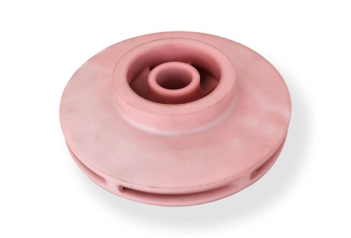
If you’ve been exploring the world of 3D printing for prototyping or production, you’ve likely come across Fusion Deposition Molding (FDM). It’s often the first technology people try—and for good reason. But is it the right choice for your specific needs?
Key takeaways
- At its core, FDM is an extrusion-based process that builds objects layer by layer using molten thermoplastic.
- Material versatility is one of FDM’s biggest draws. You’re not locked into one type of plastic.
- Beyond being accessible, FDM offers concrete benefits that solve real-world product development challenges.
- Being aware of FDM’s constraints is key to project success. Here’s what you’re signing up for:
How Does FDM 3D Printing Actually Work? The Engine Under the Hood
At its core, FDM is an extrusion-based process that builds objects layer by layer using molten thermoplastic. Imagine a high-precision, computer-controlled hot glue gun. The magic isn’t just in melting plastic—it’s in the precise coordination of temperature, movement, and material flow that turns a digital file into a physical part.
What Are the Key Components That Make an FDM Printer Tick?
Every FDM printer, from a $300 desktop model to a $50,000 industrial system, is built around a few critical components. Understanding these helps you troubleshoot issues and appreciate what you’re paying for.
- Filament Spool: This is your raw material source—a coil of solid thermoplastic wire, typically 1.75mm or 2.85mm in diameter.
- Extruder Mechanism: This is the “feeder.” It uses a motor-driven gear to push the filament toward the hot end with consistent force.
- Hot End (Liquefier & Nozzle): The heart of the system. Here, the filament is melted in a heated block (the liquefier) and extruded through a tiny nozzle. Nozzle diameter (commonly 0.4mm) is a key driver of detail and speed.
- Build Platform: The surface where the part is constructed. A heated bed is crucial for materials like ABS to prevent warping by keeping the first layers warm.
- Motion System: This controls the movement, usually via stepper motors. Most printers use a Cartesian system (X, Y, Z axes), but some industrial models use a robotic arm for greater freedom.
- Control Board & Firmware: The printer’s brain. It interprets the instructions (G-code) from your sliced file and directs all the motors and heaters.
Can You Walk Me Through the FDM Process, Step-by-Step?
The journey from idea to object is a fascinating dance between software and hardware. Here’s how it flows in practice:
- Design & Prepare (CAD to STL): It all starts with a 3D model from CAD software (like SolidWorks or Fusion 360). This model is exported as an STL file—a format that approximates the shape with a mesh of triangles.
- Slicing – The Digital Blueprint: This is a critical step. Slicing software (Cura, PrusaSlicer) cuts the STL model into hundreds of horizontal layers and generates the G-code toolpath. Here, you set layer height, infill density, print speed, and support structures.
- Material Feeding & Melting: The printer feeds the solid filament into the hot end, where it’s heated past its glass transition temperature. For PLA, that’s around 180-220°C; for advanced materials like PEEK, it can exceed 400°C.
- Layer Deposition: The nozzle moves over the build plate, depositing a thin bead of molten plastic in the pattern defined for the first layer. Cooling fans immediately start to solidify the material.
- Layer-by-Layer Buildup: After each layer, the build plate drops (or the nozzle rises) by one layer height (e.g., 0.2mm), and the next layer is deposited on top. The heat from the new layer partially fuses it to the one below.
- Supporting Complex Shapes: For overhangs greater than about 45 degrees, the printer generates temporary support structures to hold up the plastic. These can be break-away or soluble in a secondary bath.
- Post-Processing – The Finishing Touch: Once printed, the part is removed. Supports are detached, and the part might be sanded, smoothed (via vapor polishing for ABS), painted, or even annealed for higher strength.
What Materials Can You Really Use with FDM?
Material versatility is one of FDM’s biggest draws. You’re not locked into one type of plastic. The choice of filament directly dictates the part’s properties, cost, and even the printer requirements.
What Are the Most Common FDM Filaments and Their Best Uses?
| Material | Key Characteristics | Best For | Watch Out For |
|---|---|---|---|
| PLA | Easy to print, biodegradable, stiff, low warp, good detail. | Concept models, visual prototypes, educational projects, decorative items. | Low heat resistance, brittle under impact. |
| ABS | Tough, impact-resistant, higher heat resistance, can be vapor-smoothed. | Functional prototypes, enclosures, automotive trim, LEGO-like parts. | Requires a heated bed & enclosure due to warping and fumes. |
| PETG | Combines PLA’s ease with ABS’s durability. Good chemical & moisture resistance. | Mechanical parts, containers, outdoor fixtures, protective components. | Can be “stringy” during printing; less rigid than ABS. |
| TPU | Flexible, elastic, rubber-like, high impact absorption. | Gaskets, grips, dampeners, wearables, phone cases. | Requires a direct-drive extruder for reliable printing. |
| Nylon (PA) | Very strong, durable, fatigue-resistant, good for functional parts. | Gears, hinges, tooling, wear-resistant components. | Highly hygroscopic—must be stored dry; often needs >250°C hot end. |
| PC (Polycarbonate) | Extremely high strength, heat resistance, and transparency. | Engineering prototypes, high-temp applications, protective gear. | Requires very high printing temps (270-310°C) and an enclosure. |
When Should You Consider Advanced & Composite Materials?
For demanding applications, material science has supercharged FDM. In one aerospace prototyping project I consulted on, standard ABS wasn’t surviving thermal cycling tests. The switch to a carbon fiber-reinforced nylon filament provided the necessary stiffness and heat deflection temperature, allowing the prototype to validate the design under near-real conditions. These composites bridge the gap between basic plastics and manufacturing-grade materials.
- Fiber-Reinforced (CF/GF): Filaments infused with carbon fiber or glass fiber offer dramatically increased stiffness, strength, and dimensional stability. They are abrasion-resistant but require hardened steel nozzles.
- High-Performance Polymers: Materials like PEEK and ULTEM are used in aerospace, medical, and automotive for their exceptional strength, chemical resistance, and high-temperature performance. They demand specialized, high-temperature printers.
What Are the Real Advantages of Choosing FDM?
Beyond being accessible, FDM offers concrete benefits that solve real-world product development challenges.
- Cost-Effectiveness (Printer & Material): Desktop FDM printers start under $500, and even industrial systems are often an order of magnitude cheaper than equivalent SLS or metal systems. Filament cost is low, typically $20-$150/kg, keeping the cost-per-part minimal.
- Unmatched Material Variety & Speed: From the ease of PLA to the strength of composites, you can match the material to the prototype’s purpose—be it for fit, form, or function. For simple geometries, FDM is also one of the faster 3D printing methods, letting you iterate designs in hours, not days.
- Design Freedom for Complex Geometries: It enables integrated assemblies, internal channels, and lightweight lattices that are impossible with machining. I once designed a fluidics housing with internal serpentine cooling channels that could only be made as a single piece via FDM.
- Office & Workshop Friendly: Unlike SLA (which uses resins) or SLS (powder handling), FDM is relatively clean and safe for an office or lab environment with minimal venting requirements for most materials.
What Are the Honest Limitations You Need to Plan For?
Being aware of FDM’s constraints is key to project success. Here’s what you’re signing up for:
- Layer Lines & Surface Finish: The “stair-stepping” effect on curved surfaces is FDM’s trademark. Aesthetic or high-precision parts require post-processing like sanding, priming, and painting, which adds time and skill.
- Anisotropic Strength: This is a critical engineering consideration. Parts are strongest in the X-Y plane (along the layers) and weakest in the Z-axis (between layers). A hook printed vertically might snap more easily under load than one printed on its side.
- Dimensional Accuracy & Warping: While good, accuracy (±0.1-0.5% is typical) isn’t as tight as SLA or machining. Thermal shrinkage (especially in ABS) can cause corners to lift (warping), affecting flatness and tolerances.
- The Support Structure Challenge: Supports are often necessary but can damage surface finish during removal and increase material use. Soluble supports (like PVA) solve this but double the material cost and require a dual-extruder printer.
How Does FDM Stack Up Against Other 3D Printing Tech?
Choosing a technology is about trade-offs. This comparison should help position FDM in the broader landscape.
| Feature | FDM | SLA (Resin) | SLS (Powder) |
|---|---|---|---|
| Best For | Functional prototypes, tooling, low-cost parts, education. | High-detail prototypes, miniatures, molds, dental models. | Complex, durable functional parts & end-use production. |
| Surface Finish | Visible layer lines; rough. | Smooth, glass-like finish. | Grainy, sand-like finish. |
| Accuracy | Good (±0.1-0.5mm). | Excellent (±0.05-0.1mm). | Very Good (±0.1-0.3mm). |
| Material Options | Wide variety of thermoplastics. | Limited to photopolymer resins. | Primarily nylons & some polymers. |
| Strength | Moderate, Anisotropic. | Brittle, Isotropic. | Strong, Isotropic (uniform in all directions). |
| Cost (Entry) | Low ($200+) | Medium ($1,500+) | High ($50,000+) |
The Bottom Line: Use FDM for toughness and function on a budget, SLA for stunning detail and accuracy, and SLS for complex, high-strength parts without supports.
How to write a spec that gets priced correctly
A drawing is a contract. If it leaves a number open, the shop fills that number in with its own default. The default is rarely the one you had in mind. Put these five lines on every RFQ and most of the back-and-forth disappears before it starts.
- File format and units, with the model exported in millimetres
- Process and material grade, not a trade name
- Critical features and the tolerance each one needs
- Surface finish and the faces it applies to
- Quantity for the pilot build and for the year
The point is not paperwork. Each line removes a decision the shop would otherwise make for you. A complete RFQ comes back priced. An incomplete one comes back guessed.
What actually drives the price
Buyers usually push on material because it is the line they can see. In practice the material is rarely the biggest number on a quote. These five lines decide most of it:
- build volume and orientation
- layer height and support structure
- material grade and colour
- post-processing and hand finishing
- quantity per build plate
Ask for the quote split by line. A supplier who cannot break it down is guessing, and you will pay for the guess. The line you can usually renegotiate is the tolerance band, not the raw material.
Problems you will meet, and the fix
Every process has a failure mode it prefers. The same four show up again and again on this kind of work, and none of them are mysteries once you know what to look for.
- Warping on long flat faces where the part lifts off the plate
- Layer lines showing through a cosmetic surface
- Support scars on a mating face nobody flagged
- Dimensional drift on thin walls after cooling
Catch the fault on the first part, not the hundredth. A first-article check costs an hour. A bad batch costs the whole order. Write the check into the purchase order so nobody has to remember it.
What to check on the first article
The first article is the cheapest inspection you will ever buy. Use it properly and the rest of the run becomes boring, which is exactly what you want.
- Every dimension on the drawing, with the measured value written beside it.
- The material certificate, matched to the heat or lot number on the parts.
- The finish against the sample you approved, under the same light.
- Fit against the mating part, assembled rather than measured.
- Packaging, because parts that arrive damaged were never in tolerance.
Check in this order: datums, then mating features, then cosmetic faces. If the datums are wrong, every number after them is noise. Keep the report on file. When a problem shows up in month six, that document is the only thing that tells you what changed.
How to compare two quotes fairly
Two numbers are not comparable unless the scope matches. Line them up before you decide, because a low number with three gaps is not a low number.
Same drawing, same material, same finish, same inspection. Anything else is a different job wearing the same part number. Then look at what each quote leaves out. Freight, packaging, certificates and tooling are the usual gaps.
Ask each supplier to state their assumptions in writing. The one who does is usually the one who has run the process before.
Scaling from one part to a batch
The first part teaches you the process. The hundredth teaches you the process cost.
Watch three things as volume grows: setup amortisation, tool wear, and how much hand work the finish still needs. If the unit price barely moves between ten and a hundred, the cost sits in material or in hand work, not in setup. Ask which, because only one of them is negotiable.
Lead time behaves the same way. A one-off is scheduled around other jobs. A repeat order is scheduled around your forecast. Give the shop a forecast and the lead time gets shorter, not longer.
How to read a supplier's quote
A quote is a short document with a long shadow. Four things in it decide whether the job runs smoothly, and only one of them is the price.
- The scope line. It should name the process, the material and the finish, not just the part.
- The tolerance basis. General tolerance or the drawing, and which standard it follows.
- The exclusions. Tooling, freight, certificates and inspection are the usual omissions.
- The validity date. Material prices move, and an open-ended quote is a promise nobody can keep.
Read the exclusions before you read the total. A quote that leaves out tooling is not cheaper. It is a quote for a different job.
So, Where Is FDM 3D Printing Used Successfully?
FDM’s practicality makes it a workhorse across industries:
- Rapid Prototyping: The most common use. Engineers print multiple iterations in a day to test form, fit, and function.
- Manufacturing Aids: Custom jigs, fixtures, and assembly guides can be made in-house overnight, improving production line efficiency. A client saved weeks of lead time and 60% cost by switching from machined aluminum to printed composite tooling.
- Low-Volume & Bridge Production: For runs of 10-500 parts before committing to expensive injection molding tooling.
- Education & Research: Affordable, hands-on tool for STEM, allowing students to hold their designs.
- End-Use Parts: With the right material (ASA, PETG, Nylon) and design, FDM parts are used in drones, agricultural equipment, and consumer products.
Our solution for Fusion Deposition Molding (FDM) 3D
YiguProto runs 3D printing in house, from a single prototype to a production batch. We quote the process, the material and the finish as separate lines, so you can see where the money goes instead of arguing with one number.
Send a STEP file or a drawing and you get a DFM report in one to two business days. It flags the features that add cost and the features that will not hold tolerance on the process you picked.
Every order ships with an inspection report on the features you call out. If a part misses, we make it again. Ready to price a part? Start with a free quote and DFM review, or read more about our 3D printing. You can also talk to an engineer before you commit to a drawing.
FAQ about Fusion Deposition Molding (FDM) 3D
How do I compare two quotes fairly?
Match the scope first: same drawing, same material, same finish, same inspection. Then read the exclusions. Freight, tooling and certificates are the usual gaps, and a low number with three gaps is not a low number.
What is the lead time for Fusion Deposition Molding (FDM) 3D?
Expect 2 to 5 business days for a first batch. Tooling, material stock and the finishing queue all move that number, so we confirm the date in writing before the run starts rather than after.
What files do you need in order to quote?
A STEP file plus a PDF drawing that carries the same revision letter. The model carries the geometry and the drawing carries the intent. When the two disagree, the shop picks one, and it is never the one you meant.
Can Fusion Deposition Molding (FDM) 3D be made in small quantities?
Yes, and small quantities are where a good supplier earns the next order. Setup dominates the price at low volume, so the cheapest route is usually the one with the fewest operations, not the cheapest material.
What is Fusion Deposition Molding (FDM) 3D used for?
Fusion Deposition Molding (FDM) 3D turns up wherever the part has to do a real job at a predictable cost: brackets, housings, fixtures, covers and the fittings that hold them together. The honest test is whether the properties match the load and the environment, not whether the material is fashionable.
What tolerance can you hold on Fusion Deposition Molding (FDM) 3D?
The working default is ±0.1 mm on small features, ±0.3% on long spans. Tighter than that the process changes and so does the price, because every step tighter adds inspection time. Call out only the faces that mate with something else and leave the rest on the general tolerance.
The short version
Fusion Deposition Molding (FDM) 3D rewards the buyer who reads the data sheet and the drawing together. Pick the option for the property that matters, not for the price per kilo.
Tighten only what mates. Test a sample before the run. Then let the process do the rest.