
Industry Applications
Is Gear Machining the Core Cornerstone of Modern Industrial Transmission?
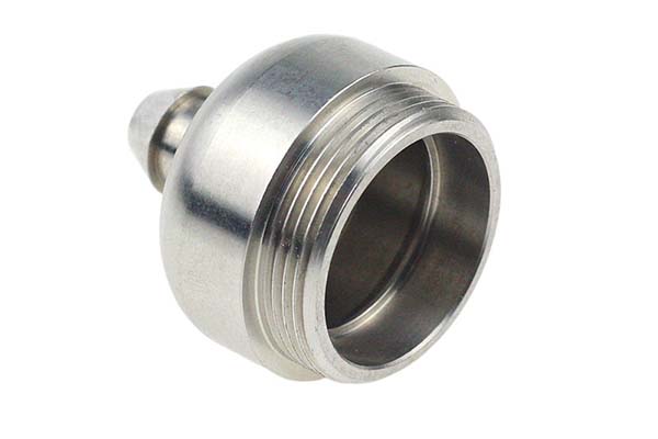
Gears are the unsung heroes of the mechanical world. Hidden inside gearboxes, engines, and drives, they are the components that actually transmit power and motion. From the transmission in your car to the massive gearboxes in a wind turbine, the quality of the gear machining directly determines the efficiency, noise level, and lifespan of the entire machine.
Key takeaways
- Choosing the right manufacturing process is a balance between precision, production volume, and cost. Here is a comparison of the most common methods.
- The machine tool and cutting tools are the direct link between your process plan and the finished part.
- For gears requiring accuracy of IT6 or better, such as those used in aerospace, advanced finishing techniques are required.
- Heat treatment is arguably the most critical and challenging step in gear manufacturing.
What Are the Basic Principles of Gear Design?
Before any metal is cut, a gear must be designed. The core design parameters are the foundation upon which every subsequent machining decision is built.
What Are the Core Design Parameters?
The performance of a gear is defined by three key parameters:
- Module (m): This determines the size of the gear teeth and its load-bearing capacity. Common modules range from 1.0mm to 50mm, standardized by organizations like AGMA and ISO.
- Pressure Angle: This is the angle of the tooth face that transmits force. The industry standard is 20°, striking a balance between strength and efficiency.
- Tooth Geometry: The most common tooth form is the involute curve, which ensures smooth, constant velocity transmission as the teeth mesh.
A critical concept in gear design is the contact ratio, which measures how many pairs of teeth are in contact at any given time. This number must be ≥ 1.2 to ensure continuous, smooth power transmission without vibration. For high-precision applications, like an automotive transmission, the accumulated tooth pitch error must be controlled to less than 0.02mm to guarantee smooth shifting.
How Do Material and Heat Treatment Affect Gears?
The choice of material is a balance between strength, wear resistance, and machinability.
- 20CrMnTi: A low-carbon alloy steel, this is the preferred material for automotive gears due to its excellent response to carburizing.
- 42CrMo: A high-strength steel commonly used for large wind turbine gears, chosen for its fatigue resistance.
Heat treatment is the critical process that unlocks a material’s potential. Carburizing and quenching is a common method that adds carbon to the surface of a low-carbon steel part. This creates a hard, wear-resistant outer layer with a surface hardness of 58-62 HRC, while the core remains tough and ductile.
A Cautionary Tale: An automotive manufacturer once substituted the specified 20CrMnTi with a standard 45# steel to save costs. The result was a dramatic drop in gear life, from 100,000 kilometers to just 30,000 kilometers. The gears failed prematurely due to surface fatigue. Replacing the material and optimizing the nitriding process eventually reduced the failure rate by 70%.
What Are the Main Gear Machining Processes?
Choosing the right manufacturing process is a balance between precision, production volume, and cost. Here is a comparison of the most common methods.
| Process | Core Strengths | Typical Accuracy (IT Grade) | Best For | Cost Level |
|---|---|---|---|---|
| Gear Hobbing | High efficiency, ideal for mass production | IT8-IT10 | Spur and helical external gears | Medium |
| Gear Shaping | Can cut internal gears and cluster gears | IT9-IT11 | Internal gears, shoulder gears | Medium-Low |
| Gear Grinding | Highest precision, best surface finish | IT4-IT6 | Aerospace, high-performance gears | High |
| Gear Shaving | Efficient finishing process | IT7-IT8 | Automotive transmission gears (pre-hardening) | Medium |
| Gear Honing | Improves surface finish, removes heat treat distortion | Ra 0.2-0.4µm | Finishing hardened gears | Medium |
| CNC Gear Milling | Flexible, good for large, special gears | IT10-IT12 | Large bevel gears, construction machinery | Low |
| Gear Broaching | Extremely fast, highly consistent | IT7-IT9 | Internal splines, sprockets | Medium-High |
| Cold Rolling | High material utilization, strong grain flow | IT8-IT9 | Small to medium modulus gears | Low |
A Real-World Process Selection Case
A new energy vehicle company needed to produce 1 million gearbox gears per year (module 3mm). They initially considered a warm forging process with a €5 million equipment investment. However, a detailed cost analysis showed that a cold forging + shaving process, despite a higher initial equipment investment of €8 million, resulted in a lower per-part cost (€10.50 vs. €12.10) and increased material utilization to 90%. The higher upfront investment paid off through significant long-term savings.
How to Select Gear Machining Equipment and Tools?
The machine tool and cutting tools are the direct link between your process plan and the finished part.
Choosing the Right Machine Tool
- CNC Gear Hobbing Machines are the workhorses of high-volume production. Key selection criteria include the module range, spindle speed (which directly impacts cycle time), and repeatability, which should be ≤ 0.003mm.
- Gear Shaping Machines are chosen based on part diameter. Vertical gear shapers are suitable for smaller gears (≤200mm), while larger gears require horizontal machines.
The Importance of Tools and Fixtures
- Cutting Tool Material: For high-volume production, carbide or PCD (polycrystalline diamond) tools are preferred, offering 5-10 times the tool life of high-speed steel (HSS).
- Grinding Wheel Dressing: In gear grinding, maintaining the wheel’s shape is critical. Using a diamond roller dresser can keep profile accuracy within 0.005mm.
- Workholding Fixtures: Precision fixtures, such as expansion arbors, are essential for maintaining concentricity. They should control radial runout to ≤ 0.002mm.
- Automation: Integrating an automatic loading and unloading system can boost production capacity by over 30% by reducing non-cutting time.
An upgrade case: A gear factory replaced an old machine with a new CNC hobbing center with an integrated loader. Their per-shift output increased from 800 to 1200 parts, and their yield rate jumped from 92% to 98.5% due to the elimination of manual loading errors.
How Is Ultra-High Precision Achieved?
For gears requiring accuracy of IT6 or better, such as those used in aerospace, advanced finishing techniques are required.
Hard Tooth Surface Finishing
The standard high-precision combination is “grinding + honing”. Grinding first corrects any distortion from heat treatment, achieving tooth profile errors ≤ 0.005mm. Honing then improves the surface finish and can remove the “grinding burn” layer.
Tooth Surface Modification
This is a key technology for reducing noise. Tip relief (removing 0.01-0.03mm of material from the tooth tip) and crowning (slightly rounding the tooth flank) help compensate for deflection under load and misalignment. Properly applied, these modifications can reduce gear noise by 3-5 dB.
Microgeometry and Balance
- Surface Finish: Controlling roughness to Ra ≤ 0.3µm reduces friction and improves efficiency.
- Dynamic Balancing: For high-speed gears, imbalance can cause catastrophic vibration. Aerospace gears often require a balance grade of G2.5, which at 30,000 RPM means a residual imbalance of less than 0.5 g·mm.
What Are the Key Steps in Gear Heat Treatment?
Heat treatment is arguably the most critical and challenging step in gear manufacturing.
Main Heat Treatment Processes
- Carburizing & Quenching: Used for low-carbon alloy steels (e.g., 20CrMnTi). It creates a hard case (58-62 HRC) of 0.8-1.5mm depth. This is the standard for automotive gears.
- Nitriding: A lower-temperature process (around 550°C) that causes minimal distortion, making it ideal for precision gears that cannot tolerate post-treatment grinding.
- Induction Hardening: A fast, energy-efficient method for locally hardening specific areas, like the teeth of large shaft gears.
- Surface Strengthening: Advanced techniques like laser cladding can apply a wear-resistant coating, increasing component life by up to 3x in harsh environments.
How to Control Heat Treatment Distortion
Distortion is a major pain point. As metal is heated and cooled, it changes shape. Strategies to control this include:
- Using isothermal quenching processes to minimize microstructural stresses.
- Designing specialized quenching fixtures to support parts during cooling.
- Allowing for distortion by leaving 0.1-0.2mm of stock on critical features to be removed by final grinding.
A wind turbine gear manufacturer successfully used these methods to reduce ring gear distortion from 0.3mm to less than 0.08mm.
How Is Gear Quality Controlled?
A robust quality system is essential to ensure every gear meets its design specifications.
Key Inspection Items and Methods
| Inspection Item | Common Method | Typical Standard (IT5) | Equipment |
|---|---|---|---|
| Tooth Profile Error | Coordinate Measuring Machine (CMM) | ≤ 0.005mm | Zeiss, Hexagon CMM |
| Tooth Lead Error | Gear Measuring Center | ≤ 0.003mm | Klingelnberg, Gleason |
| Pitch Accuracy | Single Tooth Pitch Measurement | Cumulative error ≤ 0.02mm | Gear Pitch Tester |
| Runout | Dial Indicator | ≤ 0.02mm | V-block and indicator |
| Surface Roughness | Profilometer | Ra ≤ 0.4µm | Taylor Hobson, Mitutoyo |
| Dynamic Performance | Vibration Test Analyzer | Acceleration ≤ 2.5 m/s² | B&K, Siemens |
Building a Quality Management System
A system like ISO/TS 16949 requires control at every step, including:
- Incoming Material Inspection: Using a spectrometer to verify material grade.
- Process Monitoring: Ensuring furnace temperature uniformity is ≤ ±5°C during heat treatment.
- Final Inspection: Performing 100% tooth profile inspection on critical features.
How to write a spec that gets priced correctly
A drawing is a contract. If it leaves a number open, the shop fills that number in with its own default. The default is rarely the one you had in mind. Put these five lines on every RFQ and most of the back-and-forth disappears before it starts.
- The application and the environment it runs in
- The standard the part must meet
- Process and material that can meet it
- Inspection and documentation package
- Volume and ramp schedule
The point is not paperwork. Each line removes a decision the shop would otherwise make for you. A complete RFQ comes back priced. An incomplete one comes back guessed.
What actually drives the price
Buyers usually push on material because it is the line they can see. In practice the material is rarely the biggest number on a quote. These five lines decide most of it:
- process selection
- material and certification
- tolerance band
- inspection and documentation
- volume
Ask for the quote split by line. A supplier who cannot break it down is guessing, and you will pay for the guess. The line you can usually renegotiate is the tolerance band, not the raw material.
Problems you will meet, and the fix
Every process has a failure mode it prefers. The same four show up again and again on this kind of work, and none of them are mysteries once you know what to look for.
- A consumer-grade process chosen for an industrial duty
- Documentation that arrives after the parts
- A tolerance tighter than the application needs
- No plan for the second source
Catch the fault on the first part, not the hundredth. A first-article check costs an hour. A bad batch costs the whole order. Write the check into the purchase order so nobody has to remember it.
What to check on the first article
The first article is the cheapest inspection you will ever buy. Use it properly and the rest of the run becomes boring, which is exactly what you want.
- Every dimension on the drawing, with the measured value written beside it.
- The material certificate, matched to the heat or lot number on the parts.
- The finish against the sample you approved, under the same light.
- Fit against the mating part, assembled rather than measured.
- Packaging, because parts that arrive damaged were never in tolerance.
Check in this order: datums, then mating features, then cosmetic faces. If the datums are wrong, every number after them is noise. Keep the report on file. When a problem shows up in month six, that document is the only thing that tells you what changed.
How to compare two quotes fairly
Two numbers are not comparable unless the scope matches. Line them up before you decide, because a low number with three gaps is not a low number.
Same drawing, same material, same finish, same inspection. Anything else is a different job wearing the same part number. Then look at what each quote leaves out. Freight, packaging, certificates and tooling are the usual gaps.
Ask each supplier to state their assumptions in writing. The one who does is usually the one who has run the process before.
Scaling from one part to a batch
The first part teaches you the process. The hundredth teaches you the process cost.
Watch three things as volume grows: setup amortisation, tool wear, and how much hand work the finish still needs. If the unit price barely moves between ten and a hundred, the cost sits in material or in hand work, not in setup. Ask which, because only one of them is negotiable.
Lead time behaves the same way. A one-off is scheduled around other jobs. A repeat order is scheduled around your forecast. Give the shop a forecast and the lead time gets shorter, not longer.
How to read a supplier's quote
A quote is a short document with a long shadow. Four things in it decide whether the job runs smoothly, and only one of them is the price.
- The scope line. It should name the process, the material and the finish, not just the part.
- The tolerance basis. General tolerance or the drawing, and which standard it follows.
- The exclusions. Tooling, freight, certificates and inspection are the usual omissions.
- The validity date. Material prices move, and an open-ended quote is a promise nobody can keep.
Read the exclusions before you read the total. A quote that leaves out tooling is not cheaper. It is a quote for a different job.
What Are the Future Trends in Gear Manufacturing?
The industry is moving toward greater intelligence and sustainability.
- Intelligent Manufacturing: Digital twin technology allows the entire machining process to be simulated and optimized before a single chip is cut. This can predict errors and reduce setup time. One factory reported a 40% reduction in equipment failure after implementing cloud-based machine monitoring.
- Additive Manufacturing: 3D printing is being used to create complex gear geometries with near-perfect material utilization (up to 95%).
- Green Manufacturing: Processes like dry cutting and cold rolling eliminate the need for cutting fluids, significantly reducing environmental impact. Wear-resistant coatings like TiN extend tool life by up to 5x, reducing resource consumption.
- Predictive Maintenance: AI algorithms analyze machine data to predict failures before they happen, drastically reducing unplanned downtime.
Industry data projects the global gear market to reach $165 billion by 2030, with companies that successfully implement intelligent manufacturing enjoying profit margins 15-20% higher than their traditional competitors.
Gear machining is a complex, multi-stage process that sits at the very heart of mechanical power transmission. From the initial design and material selection, through the choice of hobbing, shaping, or grinding, to the critical steps of heat treatment and final inspection, every decision impacts the performance and lifespan of the final component. As industries demand ever-higher precision, lower noise, and greater efficiency, gear manufacturers must embrace advanced technologies like tooth surface modification, digital twins, and sustainable processes. Mastering this intricate process is not just about making a part; it is about ensuring the reliability of the machines that drive our world.
Our solution for Gear Machining
YiguProto runs contract manufacturing in house, from a single prototype to a production batch. We quote the process, the material and the finish as separate lines, so you can see where the money goes instead of arguing with one number.
Send a STEP file or a drawing and you get a DFM report in one to two business days. It flags the features that add cost and the features that will not hold tolerance on the process you picked.
Every order ships with an inspection report on the features you call out. If a part misses, we make it again. Ready to price a part? Start with a free quote and DFM review, or read more about our contract manufacturing. You can also talk to an engineer before you commit to a drawing.
FAQ about Gear Machining
Is there a minimum order quantity?
No hard minimum. One part is fine. What changes with volume is which costs dominate, so a single unit is priced mostly on setup and a thousand units are priced mostly on cycle time and material.
How do I compare two quotes fairly?
Match the scope first: same drawing, same material, same finish, same inspection. Then read the exclusions. Freight, tooling and certificates are the usual gaps, and a low number with three gaps is not a low number.
What is Gear Machining used for?
Gear Machining turns up wherever the part has to do a real job at a predictable cost: brackets, housings, fixtures, covers and the fittings that hold them together. The honest test is whether the properties match the load and the environment, not whether the material is fashionable.
What files do you need in order to quote?
A STEP file plus a PDF drawing that carries the same revision letter. The model carries the geometry and the drawing carries the intent. When the two disagree, the shop picks one, and it is never the one you meant.
How long does a first article take?
Usually a few business days once the drawing is frozen, and longer if tooling is involved. The date we give you is the date we confirm in writing, not the date we hope for.
What tolerance can you hold on Gear Machining?
The working default is ±0.05 mm to ±0.1 mm depending on process. Tighter than that the process changes and so does the price, because every step tighter adds inspection time. Call out only the faces that mate with something else and leave the rest on the general tolerance.
The short version
Gear Machining rewards the buyer who reads the data sheet and the drawing together. Pick the option for the property that matters, not for the price per kilo.
Tighten only what mates. Test a sample before the run. Then let the process do the rest.