
3D Printing
How Can You Make Your 3D Printed Parts Stronger?
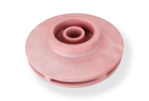
Achieving high load-bearing capacity in 3D prints requires a holistic approach that integrates design strategy, material science, process optimization, and post-processing. This guide moves beyond basic infill adjustments to provide a systematic framework for engineers and makers.
Key takeaways
- Strength begins in the CAD model. Intelligent design directs stress away from weak points and uses geometry to enhance performance.
- Material choice sets the upper limit of your part’s potential strength. Different polymers and composites serve different needs.
- Your slicer settings are where theoretical strength becomes reality. These parameters directly control the integrity of the part.
- Yes, the process doesn’t end at the printer. Several post-processing techniques can “lock in” or enhance strength.
How Can Design Itself Create Strength?
Strength begins in the CAD model. Intelligent design directs stress away from weak points and uses geometry to enhance performance.
- Topology Optimization: This is a generative design process where software removes material from areas of low stress, creating organic, lightweight structures that are inherently strong. Think of the hollow, branching structure of a femur bone. Tools like Autodesk Fusion 360’s Generative Design or nTopology can perform this analysis. For example, a motor mount redesigned with topology optimization can maintain rigidity while using 40% less material, concentrating strength exactly where load paths demand it.
- Fillet Radii and Avoiding Sharp Corners: Stress concentrators are the enemy of strength. A sharp 90-degree interior corner creates a focal point for stress, often initiating failure. Adding a fillet radius (a curved interior corner) of even 2-3mm distributes stress along a curve, dramatically increasing the part’s fatigue life and ultimate load capacity. This is a critical, yet often overlooked, step.
- Orientation for Load Direction: This is the most crucial design-for-manufacturing decision. Always orient your part so that the primary tensile or compressive load is applied parallel to the build plate (XY-plane). Forces should run along the layer lines, not across them. For instance, a hook should be printed upright so the pulling force acts on the strong side of each layer, not trying to peel them apart.
Which Materials Offer the Best Strength?
Material choice sets the upper limit of your part’s potential strength. Different polymers and composites serve different needs.
| Material | Key Strength Properties | Best For… | Critical Print Note for Strength |
|---|---|---|---|
| PETG | Excellent layer adhesion, high impact strength, good flexibility. | Functional prototypes, mechanical parts, outdoor use. | Requires precise temperature control; prone to stringing if retraction is off. |
| Nylon (PA6, PA12) | High toughness, wear resistance, good fatigue life. | Gears, hinges, parts requiring durability. | Extremely hygroscopic; must be dried before printing (<0.1% moisture). |
| ASA/ABS | Good overall strength, heat resistance, can be vapor-smoothed. | Automotive parts, enclosures, functional assemblies. | Requires a heated enclosure to prevent warping and ensure layer bonding. |
| Polycarbonate (PC) | Very high strength and stiffness, excellent heat resistance. | Engineering components, high-stress fixtures. | Requires a high-temperature hotend (often >280°C) and an enclosure. |
| Fiber-Reinforced (CF, GF) | Carbon Fiber (CF) or Glass Fiber (GF) filled filaments (e.g., Nylon-CF, PLA-CF). Greatly increased stiffness and rigidity. | Structural parts where bending must be minimized (brackets, arms). | Abrasive—requires a hardened steel nozzle. Layer adhesion can be challenging. |
Material Selection Case Study: Drone Arm:
A drone racing team needed a stiffer arm to reduce vibration. They tested:
- Standard PLA: Adequate, but brittle on impact.
- PETG: Better impact resistance, but too flexible, causing “jello” in video.
- Carbon Fiber Reinforced Nylon: Provided the high stiffness and strength needed, drastically improving flight stability. The trade-off was a more abrasive material and the need for careful print drying.
What Print Parameters Are Non-Negotiable?
Your slicer settings are where theoretical strength becomes reality. These parameters directly control the integrity of the part.
1. Layer Adhesion: The Foundation of Strength
Strong layers are the most critical factor. This is controlled by:
- Print Temperature: Printing at the higher end of your material’s recommended range (e.g., 245°C for PETG instead of 230°C) increases polymer chain diffusion between layers. A study on PLA showed a 15% increase in inter-layer strength when printing 15°C above the standard minimum.
- Layer Height: Thinner layers (0.12mm – 0.16mm) create more contact area between layers, improving adhesion. However, they increase print time. For ultimate strength, a 0.1mm layer height can be used, though diminishing returns set in quickly.
- Print Speed: Slower external perimeters (25-40 mm/s) allow more complete melting and bonding. High speed can lead to under-extrusion and weak layers.
2. Infill Strategy: More Than Just Percentage
While infill percentage matters, the pattern is equally important.
- Gyroid vs. Grid: For load-bearing parts, Gyroid or Cubic infill patterns are superior to simple Grid. They provide multi-directional support and better resistance to complex stresses. For pure compressive loads, Tri-Hexagon or Cubic Subdivision are excellent.
- Infill Density: For functional parts, 40-60% is a robust starting point. Going to 80% or 100% (solid) offers diminishing strength returns for a large increase in material and time. Use variable infill density in your slicer to add more material only in high-stress zones.
3. Shells/Perimeters: The Primary Load Bearer
The outer walls (perimeters) carry most of the bending and torsional stress. Increasing the number of perimeters is often more effective for strength than increasing infill.
- Rule of Thumb: Use at least 3-4 perimeters for any load-bearing part. For high-stress areas, 5-6 perimeters create a thick, solid shell that is extremely strong. A part with 4 perimeters and 30% infill can be stronger than one with 2 perimeters and 80% infill.
Can Post-Processing Truly Increase Strength?
Yes, the process doesn’t end at the printer. Several post-processing techniques can “lock in” or enhance strength.
- Annealing (Heat Treating): For semi-crystalline polymers like Nylon, PETG, and some PLAs, controlled annealing can significantly increase strength and heat resistance. The process involves slowly heating the part in an oven (e.g., 80°C for PLA, 100°C for PETG) for a set time, allowing the polymer chains to crystallize further. Properly annealed PETG parts can see a 40% increase in heat deflection temperature and improved layer fusion. Crucially, parts will shrink and may warp, so this must be accounted for in the design or done before final machining.
- Epoxy Coating or Resin Infusion: For FDM parts, coating with a thin layer of two-part epoxy or using a vacuum to infuse parts with low-viscosity resin fills micro-gaps between layers, creating a more monolithic structure. This is especially effective for watertightness and impact resistance.
- Acetone Vapor Smoothing (for ABS/ASA): This process gently melts the outer surface, fusing layer lines and surface pores. It creates a smooth, glossy finish that also eliminates micro-cracks that can be stress concentrators, improving overall part integrity and fatigue life.
What Advanced Techniques Push the Limits?
For mission-critical applications, advanced methods offer the highest performance.
- Continuous Fiber Reinforcement: Systems like the Markforged Mark Two or Anisoprint embed continuous strands of carbon fiber, Kevlar, or fiberglass into a plastic matrix during printing. This is a game-changer, creating parts with strength-to-weight ratios approaching aluminum. A continuous carbon fiber reinforcement placed along a load path can increase stiffness by an order of magnitude compared to standard FDM.
- Multi-Material / Dissolvable Supports: Using a dissolvable support material (like PVA or HIPS) allows for the creation of complex internal geometries and true spherical cavities that would be impossible to clean with break-away supports. This enables stronger, more optimized designs without compromise.
How to write a spec that gets priced correctly
A drawing is a contract. If it leaves a number open, the shop fills that number in with its own default. The default is rarely the one you had in mind. Put these five lines on every RFQ and most of the back-and-forth disappears before it starts.
- File format and units, with the model exported in millimetres
- Process and material grade, not a trade name
- Critical features and the tolerance each one needs
- Surface finish and the faces it applies to
- Quantity for the pilot build and for the year
The point is not paperwork. Each line removes a decision the shop would otherwise make for you. A complete RFQ comes back priced. An incomplete one comes back guessed.
What actually drives the price
Buyers usually push on material because it is the line they can see. In practice the material is rarely the biggest number on a quote. These five lines decide most of it:
- build volume and orientation
- layer height and support structure
- material grade and colour
- post-processing and hand finishing
- quantity per build plate
Ask for the quote split by line. A supplier who cannot break it down is guessing, and you will pay for the guess. The line you can usually renegotiate is the tolerance band, not the raw material.
Problems you will meet, and the fix
Every process has a failure mode it prefers. The same four show up again and again on this kind of work, and none of them are mysteries once you know what to look for.
- Warping on long flat faces where the part lifts off the plate
- Layer lines showing through a cosmetic surface
- Support scars on a mating face nobody flagged
- Dimensional drift on thin walls after cooling
Catch the fault on the first part, not the hundredth. A first-article check costs an hour. A bad batch costs the whole order. Write the check into the purchase order so nobody has to remember it.
What to check on the first article
The first article is the cheapest inspection you will ever buy. Use it properly and the rest of the run becomes boring, which is exactly what you want.
- Every dimension on the drawing, with the measured value written beside it.
- The material certificate, matched to the heat or lot number on the parts.
- The finish against the sample you approved, under the same light.
- Fit against the mating part, assembled rather than measured.
- Packaging, because parts that arrive damaged were never in tolerance.
Check in this order: datums, then mating features, then cosmetic faces. If the datums are wrong, every number after them is noise. Keep the report on file. When a problem shows up in month six, that document is the only thing that tells you what changed.
How to compare two quotes fairly
Two numbers are not comparable unless the scope matches. Line them up before you decide, because a low number with three gaps is not a low number.
Same drawing, same material, same finish, same inspection. Anything else is a different job wearing the same part number. Then look at what each quote leaves out. Freight, packaging, certificates and tooling are the usual gaps.
Ask each supplier to state their assumptions in writing. The one who does is usually the one who has run the process before.
Scaling from one part to a batch
The first part teaches you the process. The hundredth teaches you the process cost.
Watch three things as volume grows: setup amortisation, tool wear, and how much hand work the finish still needs. If the unit price barely moves between ten and a hundred, the cost sits in material or in hand work, not in setup. Ask which, because only one of them is negotiable.
Lead time behaves the same way. A one-off is scheduled around other jobs. A repeat order is scheduled around your forecast. Give the shop a forecast and the lead time gets shorter, not longer.
How to read a supplier's quote
A quote is a short document with a long shadow. Four things in it decide whether the job runs smoothly, and only one of them is the price.
- The scope line. It should name the process, the material and the finish, not just the part.
- The tolerance basis. General tolerance or the drawing, and which standard it follows.
- The exclusions. Tooling, freight, certificates and inspection are the usual omissions.
- The validity date. Material prices move, and an open-ended quote is a promise nobody can keep.
Read the exclusions before you read the total. A quote that leaves out tooling is not cheaper. It is a quote for a different job.
What to send with the first order
The first order sets the pattern for every order after it. Send a complete package once and the shop files it, and the second order takes a fraction of the time.
- A STEP or native model plus a PDF drawing carrying the same revision letter.
- The material callout by standard number, not by trade name.
- The finish and the exact faces it applies to.
- Any test the part must pass: fit, seal, drop, salt spray, dielectric.
- A contact who can answer a question inside one working day.
Then write down what was agreed. An email that confirms the material, the finish and the date is worth more than a longer purchase order that leaves them open.
How Do You Test and Validate Strength?
Don’t guess—test.
- Print and Destroy Test Coupons: The most direct method. Design simple tensile test bars or flexure test beams according to ASTM standards (like D638 or D790). Print them with your chosen settings and material, then physically test them to failure using a bench-top tester or even a calibrated weight system. This gives you baseline mechanical property data (Ultimate Tensile Strength, Modulus of Elasticity) for your specific process.
- Non-Destructive Inspection: Use a polarizing filter (like from an old LCD screen) with a bright light source to inspect clear PETG or polycarbonate prints. Stress patterns (birefringence) will appear as colored bands, visually revealing internal stress concentrations from improper print settings or design flaws.
Improving the load-bearing capacity of 3D prints is a deliberate engineering discipline, not a matter of luck. It requires a methodical approach that spans the entire workflow: from designing with stress flow in mind and selecting the appropriate high-performance material, to meticulously calibrating thermal and geometric print parameters, and finally enhancing the microstructure through post-processing. By understanding that strength is anisotropic and actively working to align the print’s inherent grain structure with the applied loads, you can transform the perceived weakness of layered manufacturing into a reliable strength. The result is the ability to confidently deploy 3D printed parts in demanding mechanical applications, unlocking the full functional potential of additive manufacturing.
How we can help
YiguProto runs 3D printing in house, from a single prototype to a production batch. We quote the process, the material and the finish as separate lines, so you can see where the money goes instead of arguing with one number.
Send a STEP file or a drawing and you get a DFM report in one to two business days. It flags the features that add cost and the features that will not hold tolerance on the process you picked.
Every order ships with an inspection report on the features you call out. If a part misses, we make it again. Ready to price a part? Start with a free quote and DFM review, or read more about our 3D printing. You can also talk to an engineer before you commit to a drawing.
Frequently asked questions
What files do you need in order to quote?
A STEP file plus a PDF drawing that carries the same revision letter. The model carries the geometry and the drawing carries the intent. When the two disagree, the shop picks one, and it is never the one you meant.
What happens if a part is out of specification?
We measure it against the same drawing you approved and, if it misses, we make it again. What matters is that the report exists, because a disagreement without data is just an opinion.
What should I check before approving the parts?
Datums first, then the features that mate, then the cosmetic faces. Ask for a dimensional report, a material certificate and a finish sample. A part can be inside every tolerance and still not fit, so assemble one before you sign.
How long does a first article take?
Usually a few business days once the drawing is frozen, and longer if tooling is involved. The date we give you is the date we confirm in writing, not the date we hope for.
Is there a minimum order quantity?
No hard minimum. One part is fine. What changes with volume is which costs dominate, so a single unit is priced mostly on setup and a thousand units are priced mostly on cycle time and material.
How do I compare two quotes fairly?
Match the scope first: same drawing, same material, same finish, same inspection. Then read the exclusions. Freight, tooling and certificates are the usual gaps, and a low number with three gaps is not a low number.
The short version
Good parts reward the buyer who reads the data sheet and the drawing together. Pick the option for the property that matters, not for the price per kilo.
Tighten only what mates. Test a sample before the run. Then let the process do the rest.