
Rapid Prototyping
Inside a Prototype Factory: Equipment, Workflow & How to Tour Virtually
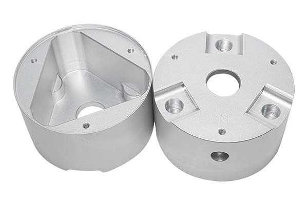
The jump from a computer design file to a real physical part is the most important and often most confusing step in making products. A carefully made computer design is just potential; a high-quality physical sample shows real progress. This article gives you an exclusive, behind-the-scenes look into the complex, high-pressure world of a modern prototype factory.
Key takeaways
- A modern prototype factory is completely different from a mass-production facility.
- To truly understand a prototype factory, we must follow a part’s journey from a block of raw material to a finished component ready for shipping.
- A prototype factory’s capability is directly tied to the technology it houses.
- In today’s global landscape, physically visiting a potential manufacturing partner isn’t always possible.
What Makes Up a Modern Prototype Factory?
A modern prototype factory is completely different from a mass-production facility. Its main mission is not cost-per-unit at large scale, but speed, accuracy, and quick changes for new product development. While a production plant is built for low-variety, high-volume output, a prototype shop succeeds with high-variety, low-volume complexity. It’s a space designed for solving problems, not just repeating tasks.
Success in this environment depends on three connected pillars:
- Skilled People: Expert machine operators, computer programming specialists, and quality control engineers who can understand complex designs and make important decisions quickly.
- Clear Processes: A strict, documented workflow that makes sure every part, from one piece to one hundred, meets the same standard of quality and tracking.
- Advanced Technology: The hardware and software that enable the precision, complexity, and speed required for modern product development cycles.
These pillars work together to create a system built for innovation.
What Is the Step-by-Step Prototyping Workflow?
To truly understand a prototype factory, we must follow a part’s journey from a block of raw material to a finished component ready for shipping. This is not an automated, hands-off process; it’s a carefully planned sequence of operations requiring expertise at every stage.
Stage 1: How Is Raw Material Prepared?
The journey begins not with a machine, but with a solid block of metal or plastic at the material staging area. This is the first critical decision point. The choice between Aluminum 6061-T6 for general-purpose strength and 7075-T6 for high-stress aerospace applications, or between Stainless Steel 304 for rust resistance and 316 for marine environments, is determined by the project’s engineering requirements.
Once the material is selected from certified stock, it’s cut to a manageable “blank” size on a precision saw. This blank is slightly larger than the final part to allow for holding and the removal of material during machining. Each blank is labeled and grouped with its matching job traveler document, which will follow it throughout the entire production process, ensuring full tracking.
Stage 2: What Happens on the Machining Floor?
The prepared blank then moves to the heart of the factory: the machining floor. Guided by the job traveler and the digital computer program, it’s assigned to the right machine. This is where the raw form is violently and precisely carved into the intended shape. The air is filled with the high-pitched sound of cutting tools and the smell of coolant.
A simple bracket might go to a 3-axis mill, while a complex medical device housing with curved surfaces will be loaded into a 5-axis machining center. The machine operator secures the blank in a clamp or custom fixture, checks the tool and program information, and starts the cycle. Metal chips fly as the machine executes thousands of lines of computer code, methodically shaping the part. For a complex component, this stage can involve multiple setups and different machines to create all the necessary features.
Stage 3: What Happens in the Quality Control Lab?
Once the primary machining operations are complete, the part does not go to finishing. It makes a required stop in the climate-controlled Quality Control (QC) lab. This step cannot be skipped. Here, the part is cleaned and allowed to adjust to the room temperature to ensure accurate measurement.
A quality engineer uses a variety of measuring tools to inspect the part against the critical dimensions and tolerances specified on the 2D engineering drawing and the 3D computer model. This isn’t just a visual check; it’s a data-driven verification process. Is the 10mm hole actually 10.01mm? Is the flatness of a critical surface within the 0.05mm tolerance? Every feature is checked, and the results are documented in a formal inspection report. If any dimension is out of spec, the part is flagged, and a problem report is created to determine the root cause.
Stage 4: How Does Finishing and Shipping Work?
Only after a part passes QC does it proceed to the final stage. The “as-machined” part often has sharp edges (burrs) that need to be carefully removed by hand in a process called deburring. It may also require post-processing finishes specified by the client. This could include anodizing for aluminum parts to add a durable, colored, and rust-resistant layer; powder coating for steel parts to provide a tough, decorative finish; or bead blasting to create a uniform matte texture.
After finishing, the part may undergo a final QC check to ensure the finishing process didn’t affect any critical dimensions. Finally, it’s carefully cleaned, wrapped, and packaged in a custom-fit box with plenty of protection to prevent any damage during shipping. The inspection report is often included in the shipment, providing the client with documented proof that the part they are holding matches the design they submitted.
This entire workflow can be visualized as:
Raw Material Staging → Machining → Quality Control → Finishing & Shipping
What Are the Essential Machines on the Shop Floor?
A prototype factory’s capability is directly tied to the technology it houses. The “arsenal” of machinery on the shop floor determines the complexity, precision, and types of materials it can handle. Here are the must-have machines for a versatile operation.
What Are 3-Axis and 5-Axis CNC Milling?
These are the workhorses of any prototype shop. CNC (Computer Numerical Control) milling centers use rotating cutters to remove material from a stationary workpiece.
- 3-axis mills move the tool or the part along the X, Y, and Z linear axes. They are perfect for creating simpler, box-shaped parts like brackets, plates, and simple housings.
- 5-axis mills add two rotational axes to the three linear axes. This allows the cutting tool to approach the workpiece from a full 360-degree range of angles. This capability is transformative. It enables the machining of highly complex shapes and organic curves in a single setup. This single-setup machining drastically improves accuracy by eliminating the potential for tolerance stack-up errors that can occur when a part is manually re-positioned for multiple operations.
| Feature | 3-Axis CNC Milling | 5-Axis CNC Milling |
|---|---|---|
| Complexity | Best for box-shaped parts with features on 6 or fewer faces. | Ideal for complex, curved surfaces and organic shapes. |
| Setup Time | Often requires multiple setups to access all features. | Can machine 5 sides of a part in a single setup. |
| Accuracy | Good, but susceptible to tolerance stack-up from re-positioning. | Excellent, as single-setup machining minimizes alignment errors. |
| Ideal Use Cases | Brackets, plates, simple enclosures. | Impellers, turbines, medical implants, complex housings. |
What Is Electrical Discharge Machining (EDM)?
EDM is a non-traditional machining process that uses a series of rapid, recurring electrical discharges (sparks) to erode material. It’s not about cutting with force; it’s about vaporizing material with thermal energy. Its primary use in a prototype factory is to create features that are impossible to achieve with conventional milling. This includes sharp internal corners, deep and narrow ribs, or complex shapes in materials that are too hard to machine conventionally, like hardened tool steel.
What Is a CNC Press Brake?
While milling and EDM cut and shape material, the CNC press brake forms it. This machine is essential for sheet metal prototyping. It uses a punch and a die to precisely bend flat sheets of metal (like aluminum, steel, or stainless steel) into 3D shapes. This is critical for creating parts like server chassis, electronic enclosures, mounting brackets, and custom panels. Without an in-house press brake, a factory cannot effectively produce a huge category of common prototype components.
What Is the Digital Backbone of a Prototype Factory?
The physical machines are only half of the equation. A modern prototype factory runs on a sophisticated software stack that forms a “digital thread,” ensuring a seamless flow of information from the client’s design file to the final inspected part.
What Is CAD?
CAD (Computer-Aided Design) is the starting point. The client’s CAD file is the blueprint for the entire manufacturing process. We work with 3D models created in software like SolidWorks, Fusion 360, or CATIA. The most effective formats for data exchange are universal, solid-based files like STEP, IGES, or Parasolid. A clean, well-modeled CAD file is the foundation for a successful outcome.
What Is CAM?
CAM (Computer-Aided Manufacturing) software is the critical bridge between the digital design and the physical machine. A skilled CAM programmer imports the client’s CAD model and uses the software to develop the manufacturing strategy. This is where immense expertise comes into play. The programmer defines the toolpaths—the exact route the cutting tool will take—and selects the appropriate cutting tools, spindle speeds, feed rates, and depth of cuts. This process generates the G-code, the machine-readable language that instructs the CNC mill on every move it needs to make.
What Is an MES?
If CAM is the bridge, the MES (Manufacturing Execution System) is the factory’s brain and central nervous system. An MES is a comprehensive software platform that manages and monitors all work-in-progress on the shop floor. When a new job is created, it’s entered into the MES, which then schedules it on the appropriate machines based on availability and priority. As the part moves through the workflow, its status is updated in real-time. This provides a single source of truth for the entire team, allowing project managers to track progress and provide clients with accurate delivery estimates. A factory with a robust MES is more organized, predictable, and transparent.
How Is Quality Verified in the QC Lab?
Making a part is one thing; proving it’s correct is another. The QC lab is where a factory demonstrates its commitment to quality through data-driven verification. This process relies on highly specialized and calibrated measuring equipment.
What Is a Coordinate Measuring Machine (CMM)?
The CMM (Coordinate Measuring Machine) is the gold standard for dimensional inspection. It’s a device that measures the geometry of physical objects with extreme precision. The machine uses a highly sensitive probe to touch discrete points on the part’s surface. By combining these points, it creates a 3D map of the feature being measured. This digital map is then compared directly against the original CAD model data. The power of a CMM lies in its ability to measure features that are difficult or impossible to check with hand tools, such as the true position of a hole or the profile of a surface.
What Are 3D Laser Scanners?
While a CMM excels at high-precision point-based measurement, a 3D laser scanner excels at capturing vast amounts of data from complex surfaces very quickly. The scanner projects a line of laser light onto the part, and cameras record its deformation to create a dense “point cloud” representing the part’s surface. Laser scanners are ideal for verifying the shape of freeform or organic surfaces, like those found on ergonomic grips or aerodynamic bodies. They are also invaluable for reverse engineering, where a physical part needs to be digitized into a CAD model.
How Can You Tour a Prototype Factory Virtually?
In today’s global landscape, physically visiting a potential manufacturing partner isn’t always possible. However, a well-structured virtual tour can be just as insightful as an in-person visit if you know what to ask for. It allows you to audit a factory’s real-world capabilities, organization, and culture.
What Should Be on Your Virtual Tour Checklist?
Demand more than a pre-recorded marketing video. A proper virtual tour is a live, interactive session that gives you an unfiltered look at the factory’s current state.
- Live, Unedited Video Feed: Insist on a live video call from a mobile device. This ensures you are seeing the shop floor as it is right now, not as it was on a perfect day months ago.
- Walkthrough of the Workflow: Ask your guide to physically walk the path of a part. Start at the raw material racks, move to a CNC machine that is currently running a job, proceed to the deburring area, and end in the QC lab.
- Focus on Organization: Pay close attention to the environment. Is the shop floor clean and well-lit? A clean, organized shop is a direct indicator of a disciplined and efficient operation.
- Dedicated Communication Channel: Suggest setting up a temporary Slack or Teams channel for the session. This allows multiple stakeholders from your team to ask questions in real-time.
- Talk to the Team: Request a brief chat with the shop floor manager or a lead machinist. Their ability to speak knowledgeably about a current job is a powerful sign of expertise.
What Questions Reveal a Factory’s True Capacity?
Any factory can send you a list of their machines. The best partners, however, can answer tough, process-oriented questions that reveal their true capabilities.
- “Can you walk me through a time you had to solve a difficult manufacturing challenge for a client’s prototype?” This probes their problem-solving ability.
- “What is your process for DFM (Design for Manufacturability) feedback?” This reveals their proactiveness. A great factory doesn’t just blindly make what you send them; they act as a partner.
- “How do you manage and communicate schedule changes or potential delays?” This assesses their transparency. A strong partner will have a clear process for communicating issues early.
- “What information is included in your standard inspection report?” This cuts to the heart of their quality philosophy. A detailed report with actual measured values demonstrates a serious commitment to quality.
- “Who will be my single point of contact, and what is their technical background?” This clarifies the communication structure. You need a dedicated project manager who can understand your technical requirements.
Understanding the inner workings of a prototype factory transforms the process of sourcing from a simple transaction into a strategic decision. By comprehending the workflow from raw material to shipping, knowing the purpose of key machines like 5-axis mills and CMMs, and appreciating the digital thread that connects it all, you move from being just a client to an informed partner. Choosing a prototype factory is not about buying a part; it’s about selecting a team of experts who will help you navigate the complexities of product development. Armed with this knowledge and the right questions to ask, you are now equipped to make a far more confident and successful decision, finding a true partner to bring your vision to life.
How we can help
YiguProto runs rapid prototyping in house, from a single prototype to a production batch. We quote the process, the material and the finish as separate lines, so you can see where the money goes instead of arguing with one number.
Send a STEP file or a drawing and you get a DFM report in one to two business days. It flags the features that add cost and the features that will not hold tolerance on the process you picked.
Every order ships with an inspection report on the features you call out. If a part misses, we make it again. Ready to price a part? Start with a free quote and DFM review, or read more about our rapid prototyping. You can also talk to an engineer before you commit to a drawing.
Frequently asked questions
How do I compare two quotes fairly?
Match the scope first: same drawing, same material, same finish, same inspection. Then read the exclusions. Freight, tooling and certificates are the usual gaps, and a low number with three gaps is not a low number.
What files do you need in order to quote?
A STEP file plus a PDF drawing that carries the same revision letter. The model carries the geometry and the drawing carries the intent. When the two disagree, the shop picks one, and it is never the one you meant.
Does the process work for prototypes as well as production?
Yes, and that is usually the point. Running the prototype on the production process removes a whole class of surprises, because the part you test is made the same way as the part you sell.
How long does a first article take?
Usually a few business days once the drawing is frozen, and longer if tooling is involved. The date we give you is the date we confirm in writing, not the date we hope for.
Is there a minimum order quantity?
No hard minimum. One part is fine. What changes with volume is which costs dominate, so a single unit is priced mostly on setup and a thousand units are priced mostly on cycle time and material.
What happens if a part is out of specification?
We measure it against the same drawing you approved and, if it misses, we make it again. What matters is that the report exists, because a disagreement without data is just an opinion.
The short version
Good parts reward the buyer who reads the data sheet and the drawing together. Pick the option for the property that matters, not for the price per kilo.
Tighten only what mates. Test a sample before the run. Then let the process do the rest.