
3D Printing
Why Should You Choose SLM for Your Metal Prototype?
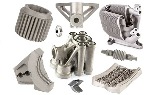
Selective Laser Melting (SLM) is a powder bed fusion additive manufacturing technology that produces fully dense, high-strength metal prototypes directly from 3D CAD data, enabling the fabrication of complex geometries that are impossible or prohibitively expensive with traditional methods.
Key takeaways
- For decades, creating a metal prototype meant a difficult choice: wait weeks for a costly investment casting mold or accept the design limitations of CNC machining, which struggles with internal channels, organic lattices, and complex assemblies.
- Understanding the core mechanism demystifies its capabilities and limitations.
- The value of SLM extends far beyond “complex shapes.” It offers a systemic advantage in product development.
- SLM is not a general-purpose solution; it excels in high-value, high-complexity domains. The table below highlights prime applications:
Introduction: The Paradigm Shift in Metal Prototyping
For decades, creating a metal prototype meant a difficult choice: wait weeks for a costly investment casting mold or accept the design limitations of CNC machining, which struggles with internal channels, organic lattices, and complex assemblies. SLM metal 3D printing changes this calculus. By using a high-powered laser to selectively melt fine metal powder layer by layer, SLM builds parts with near-net-shape accuracy and material properties comparable to wrought material. This guide cuts through the technical complexity to provide engineers and procurement specialists with a clear, actionable understanding of SLM’s capabilities, process, and economic value, empowering smarter, faster development decisions.
How Does the SLM Process Actually Work?
Understanding the core mechanism demystifies its capabilities and limitations. SLM is a precise, thermally-driven process conducted in an inert argon or nitrogen atmosphere to prevent oxidation.
- Powder Recoating: A recoater blade or roller spreads a thin layer of metal powder (typically 20-60 microns thick) across the build platform.
- Selective Laser Melting: A high-precision fiber laser (often 200W to 1kW) scans the cross-section of the part defined by the sliced CAD file, completely melting the powder particles to form a solid layer. The laser path is meticulously planned to manage thermal stress.
- Platform Lowering & Iteration: The build platform lowers by one layer thickness, a new powder layer is applied, and the laser melting repeats, fusing to the previous layer.
- Post-Process Isolation: The part is fully encapsulated in unfused powder during the build, which acts as natural support for overhangs and conducts heat away. After the build, the entire “powder cake” is removed from the machine for part extraction.
What Are the Key Benefits for Engineering and Procurement?
The value of SLM extends far beyond “complex shapes.” It offers a systemic advantage in product development.
- Unprecedented Design Freedom (Topology Optimization & Consolidation): Engineers can use generative design and topology optimization software to create organic, lightweight structures that meet performance requirements with minimal material. A classic example is consolidating an assembly of dozens of parts into a single, monolithic SLM component, eliminating fasteners, seals, and assembly labor. GE’s famous fuel nozzle for the LEAP engine consolidated 20 parts into 1, improving performance and durability.
- Accelerated Development Timelines: The direct digital-to-part path eliminates tooling. Lead times shift from 6-12 weeks for tooled casting to 5-15 days for SLM. This allows for more design iterations within the same timeframe, enabling agile prototyping and faster failure analysis, ultimately de-risking the development cycle.
- Performance-Enhancing Internal Features: SLM can fabricate conformal cooling channels inside injection molds or turbine blades that follow the part’s contour, drastically improving cooling efficiency. It can also create internal lattice structures for lightweighting or specific energy absorption profiles.
- Material Efficiency for High-Value Alloys: Unlike subtractive CNC machining, which can waste over 95% of a titanium billet as chips, SLM is additive. Unused powder is sieved and recycled for future builds (with proper management), making it exceptionally economical for expensive materials like Ti-6Al-4V, Inconel 718, or cobalt-chrome.
Which Industries and Applications Benefit Most?
SLM is not a general-purpose solution; it excels in high-value, high-complexity domains. The table below highlights prime applications:
| Industry | Primary Applications | Common Materials | Key Driver for SLM Use |
|---|---|---|---|
| Aerospace & Defense | Lightweight structural brackets, turbine blades with cooling channels, complex ducting, satellite components. | Ti-6Al-4V, AlSi10Mg, Inconel 718, Scalmalloy®. | Weight reduction (directly saving fuel), part consolidation, and performance-optimized geometries. |
| Medical & Dental | Patient-specific implants (cranial, spinal, pelvic), surgical guides and instruments, porous structures for osseointegration. | Ti-6Al-4V (ELI), CoCr alloys, 316L Stainless Steel. | Customization for patient anatomy and creation of biocompatible porous surfaces that promote bone ingrowth. |
| Automotive (High-Performance) | Formula 1 & motorsport components (suspension arms, heat exchangers), custom fluid handling parts for prototyping. | AlSi10Mg, Maraging Steel, Ti-6Al-4V. | Rapid iteration for testing and low-volume production of optimized parts where cost is secondary to performance. |
| Industrial & Energy | Conformal-cooled injection molds, lightweight robotic end-effectors, turbine components, complex valves and manifolds. | H13 Tool Steel, Maraging Steel, Copper Alloys, Inconel. | Improved efficiency (e.g., faster mold cycle times) and manufacturing of previously unmachinable monolithic parts. |
What Is the Complete SLM Prototype Workflow? (From File to Part)
A successful prototype requires collaboration across a defined process.
- Design for Additive Manufacturing (DfAM): This is the most critical engineering phase. It involves: Orientation Optimization: Positioning the part to minimize supports, manage thermal stress, and achieve the best surface finish on critical faces. Support Structure Design: Creating necessary supports to anchor overhangs, conduct heat, and prevent warping. Supports are manually or automatically designed and must be removable. Hollowing & Wall Thickness: Designing internal drain holes for powder removal and ensuring minimum wall thicknesses (~0.4-0.6mm for most metals) are maintained.
- File Preparation & Build Simulation: The oriented, supported file is sliced. Advanced software (like Autodesk Netfabb or 3D Systems 3DXpert) is used to simulate the build, predicting thermal stress and potential failure points to adjust parameters pre-emptively.
- Machine Setup & Printing: The build plate is installed, the chamber is purged with inert gas, and the print job runs unattended, often for tens of hours.
- Post-Processing: This is a multi-step, often labor-intensive stage: Stress Relief & Heat Treatment: Parts are thermally treated in a furnace to relieve internal stresses induced during rapid melting/solidification. Support Removal: Parts are cut from the build plate via wire EDM, and supports are removed via machining or careful breaking. Surface Finishing: Options include CNC machining of critical interfaces, shot peening, vibratory finishing, hand polishing, or electropolishing to achieve the desired surface roughness (Ra).
- Inspection & Validation: Final parts undergo rigorous QA: CMM (Coordinate Measuring Machine) for dimensional accuracy, CT scanning for internal defect detection, and mechanical testing to validate material properties.
How Do You Evaluate Cost and Compare to Traditional Methods?
The economics of SLM are unique. The unit cost equation is less sensitive to geometric complexity than traditional methods.
- Cost Drivers: The primary factors are part volume (uses powder), part height (determines print time), and post-processing requirements. A small, dense, highly finished part can be more expensive than a larger, simpler one.
- The Breakeven Analysis: SLM competes not with mass production but with low-volume, high-complexity manufacturing. It becomes economical when: Traditional methods require expensive tooling (e.g., casting molds). CNC machining requires extensive programming and fixturing for complex parts. The design enables part consolidation, saving significant assembly and inventory cost. Lead time savings have a high monetary value for the project.
What Are the Current Limitations and Challenges?
A professional assessment requires acknowledging the hurdles.
- Surface Finish and Accuracy: As-built surfaces have a characteristic roughness (Ra 10-25 μm) and may show “stair-stepping” on curves. Critical functional surfaces often require secondary machining. Dimensional accuracy is typically ± 0.1% of dimension (with a ± 0.1 mm minimum).
- Size Constraints: Build volumes are limited. While industrial machines offer volumes up to 500 x 500 x 500 mm, this restricts very large parts. Multi-part assembly is a common workaround.
- Material and Process Qualification: For regulated industries (aerospace, medical), qualifying a specific SLM machine, parameter set, and powder batch for a production part is a lengthy, costly undertaking, though well-established for prototypes.
- Skill Gap: Effective use requires expertise in DfAM, metallurgy, and machine operation—a combination still in high demand.
Conclusion: SLM as a Strategic Development Tool
SLM metal 3D printing for prototyping is not merely a faster way to make a part; it is a capability that redefines what is possible in the design phase. It allows engineers to validate form, fit, and function with parts that closely mimic final production intent, even for designs that will eventually be cast or forged. For buyers, it represents a shift from managing long-lead-time tooling vendors to managing agile digital fabrication partners. The strategic imperative is clear: to innovate competitively in fields pushing the boundaries of performance, complexity, and customization, integrating SLM into the prototype workflow is becoming essential. The question is no longer “Can we make it?” but “What is the optimal design?”
How to write a spec that gets priced correctly
A drawing is a contract. If it leaves a number open, the shop fills that number in with its own default. The default is rarely the one you had in mind. Put these five lines on every RFQ and most of the back-and-forth disappears before it starts.
- File format and units, with the model exported in millimetres
- Process and material grade, not a trade name
- Critical features and the tolerance each one needs
- Surface finish and the faces it applies to
- Quantity for the pilot build and for the year
The point is not paperwork. Each line removes a decision the shop would otherwise make for you. A complete RFQ comes back priced. An incomplete one comes back guessed.
What actually drives the price
Buyers usually push on material because it is the line they can see. In practice the material is rarely the biggest number on a quote. These five lines decide most of it:
- build volume and orientation
- layer height and support structure
- material grade and colour
- post-processing and hand finishing
- quantity per build plate
Ask for the quote split by line. A supplier who cannot break it down is guessing, and you will pay for the guess. The line you can usually renegotiate is the tolerance band, not the raw material.
Problems you will meet, and the fix
Every process has a failure mode it prefers. The same four show up again and again on this kind of work, and none of them are mysteries once you know what to look for.
- Warping on long flat faces where the part lifts off the plate
- Layer lines showing through a cosmetic surface
- Support scars on a mating face nobody flagged
- Dimensional drift on thin walls after cooling
Catch the fault on the first part, not the hundredth. A first-article check costs an hour. A bad batch costs the whole order. Write the check into the purchase order so nobody has to remember it.
What to check on the first article
The first article is the cheapest inspection you will ever buy. Use it properly and the rest of the run becomes boring, which is exactly what you want.
- Every dimension on the drawing, with the measured value written beside it.
- The material certificate, matched to the heat or lot number on the parts.
- The finish against the sample you approved, under the same light.
- Fit against the mating part, assembled rather than measured.
- Packaging, because parts that arrive damaged were never in tolerance.
Check in this order: datums, then mating features, then cosmetic faces. If the datums are wrong, every number after them is noise. Keep the report on file. When a problem shows up in month six, that document is the only thing that tells you what changed.
How to compare two quotes fairly
Two numbers are not comparable unless the scope matches. Line them up before you decide, because a low number with three gaps is not a low number.
Same drawing, same material, same finish, same inspection. Anything else is a different job wearing the same part number. Then look at what each quote leaves out. Freight, packaging, certificates and tooling are the usual gaps.
Ask each supplier to state their assumptions in writing. The one who does is usually the one who has run the process before.
Scaling from one part to a batch
The first part teaches you the process. The hundredth teaches you the process cost.
Watch three things as volume grows: setup amortisation, tool wear, and how much hand work the finish still needs. If the unit price barely moves between ten and a hundred, the cost sits in material or in hand work, not in setup. Ask which, because only one of them is negotiable.
Lead time behaves the same way. A one-off is scheduled around other jobs. A repeat order is scheduled around your forecast. Give the shop a forecast and the lead time gets shorter, not longer.
FAQ: Your SLM Prototype Questions Answered
Q: How do the mechanical properties of SLM parts compare to cast or wrought material?
A: They are excellent but anisotropic. In the XY plane (parallel to layers), tensile strength and yield strength are typically equal to or exceed wrought values. In the Z-direction (build direction), properties can be slightly lower (~10-15%) due to layer boundaries. Fatigue performance is highly dependent on surface finish. With proper heat treatment (e.g., hot isostatic pressing – HIP), fatigue properties can meet or exceed cast equivalents.
Q: Can SLM prototypes be used for end-use production, or are they only for testing?
A: Absolutely for end-use. This is known as “Direct Part Production” or “Additive Manufacturing.” SLM is increasingly used for low-volume, high-value production in aerospace (brackets, nozzles) and medical (implants). The prototype process is identical to the production process, making the transition seamless.
Q: What is the minimum feature size and wall thickness achievable with SLM?
A: This depends on the material and machine, but as a general rule: Minimum wall thickness is around 0.3-0.4 mm for most alloys. Minimum unsupported feature size (like a pin) is about 0.5-0.7 mm. Fine details like text should have a line width > 0.8 mm and depth > 0.3 mm.
Q: How do you handle powder removal from internal channels?
A: This is a crucial DfAM consideration. All internal cavities must have escape holes for powder removal. The design must avoid “trapped powder” scenarios. For complex internal networks, multiple drain holes are designed, often to be plugged post-process. Ultrasonic cleaning and specialized powder recovery systems are used.
Our solution for Choose SLM
YiguProto runs 3D printing in house, from a single prototype to a production batch. We quote the process, the material and the finish as separate lines, so you can see where the money goes instead of arguing with one number.
Send a STEP file or a drawing and you get a DFM report in one to two business days. It flags the features that add cost and the features that will not hold tolerance on the process you picked.
Every order ships with an inspection report on the features you call out. If a part misses, we make it again. Ready to price a part? Start with a free quote and DFM review, or read more about our 3D printing. You can also talk to an engineer before you commit to a drawing.
FAQ about Choose SLM
Is there a minimum order quantity?
No hard minimum. One part is fine. What changes with volume is which costs dominate, so a single unit is priced mostly on setup and a thousand units are priced mostly on cycle time and material.
What material should I specify?
Specify by standard, not by trade name. A trade name can change under you between two orders; a standard number cannot. Then add the one property that actually decides the part, whether that is strength, heat resistance or chemical exposure.
What should I check before approving the parts?
Datums first, then the features that mate, then the cosmetic faces. Ask for a dimensional report, a material certificate and a finish sample. A part can be inside every tolerance and still not fit, so assemble one before you sign.
Can Choose SLM be made in small quantities?
Yes, and small quantities are where a good supplier earns the next order. Setup dominates the price at low volume, so the cheapest route is usually the one with the fewest operations, not the cheapest material.
What files do you need in order to quote?
A STEP file plus a PDF drawing that carries the same revision letter. The model carries the geometry and the drawing carries the intent. When the two disagree, the shop picks one, and it is never the one you meant.
What is the lead time for Choose SLM?
Expect 2 to 5 business days for a first batch. Tooling, material stock and the finishing queue all move that number, so we confirm the date in writing before the run starts rather than after.
The short version
Choose SLM rewards the buyer who reads the data sheet and the drawing together. Pick the option for the property that matters, not for the price per kilo.
Tighten only what mates. Test a sample before the run. Then let the process do the rest.