
Die Casting
What Are the Causes and Solutions of Die Casting Product Sink?
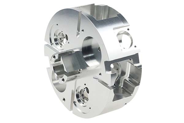
If you work with die casting, you have probably seen sink marks on your parts. These smooth, sunken areas usually appear in thick sections. They ruin the look of your products and can hide bigger problems inside. In mass production, sink defects scrap 5–8% of parts—a huge cost over time. For pressure-tight components like hydraulic valves, sinks can cause leaks or complete failure. So what causes these dents?
Key takeaways
- Sink marks (also called dents or shrinkage depressions) are smooth, sunken areas on casting surfaces. They typically range from 0.1mm to 2mm deep.
- Not all sinks are the same. Their location and appearance tell you what caused them.
- Sinks follow a simple chain of events: uneven solidification → metal shrinks → no metal to fill the gap → surface collapses.
- Fixing sinks requires a systematic approach. Address each cause area with specific solutions.
What Are Die Casting Sink Marks?
Sink marks (also called dents or shrinkage depressions) are smooth, sunken areas on casting surfaces. They typically range from 0.1mm to 2mm deep. Unlike rough defects, sinks have smooth edges and look like someone pressed a thumb into soft metal.
Where Do Sinks Appear?
Sinks always form in thick sections or at wall thickness transitions. Common locations include:
- Ribs and bosses (thick cores)
- Where thin walls meet thick walls (9mm to 3mm transitions)
- Intersections of multiple ribs (hot joints)
- Large flat surfaces with thick areas underneath
Why Should You Care About Sinks?
| Impact Area | What Happens |
|---|---|
| Appearance | Parts look defective. For visible products (auto trim, electronics), sinks mean rejection. |
| Strength | Sinks weaken the part locally. Load capacity drops by 10–25% in affected areas. |
| Pressure tightness | In valves or housings, sinks can connect to internal voids, causing leaks. |
| Machining | Sinks may not clean up during machining, ruining the final part. |
What Are the Different Types of Sink Marks?
Not all sinks are the same. Their location and appearance tell you what caused them.
| Sink Type | What It Looks Like | Where It Happens | How Bad? |
|---|---|---|---|
| Localized thick-wall sink | Small round dents (2–10mm wide), smooth edges | Thick ribs, bosses, where wall thickness changes | 4/5 (weakens part, visible) |
| Hot-joint sink | Irregular long dents, often connected to internal voids | Where multiple ribs meet (battery frame corners) | 5/5 (indicates internal holes, unsafe) |
| Surface layer sink | Shallow widespread dents (<0.5mm deep) | Large flat surfaces (covers, panels) | 2/5 (only cosmetic) |
| Post-cooling sink | Appears hours or days after casting | Very thick parts (heavy equipment brackets) | 3/5 (unpredictable, hard to catch) |
What Causes Die Casting Sink Marks?
Sinks follow a simple chain of events: uneven solidification → metal shrinks → no metal to fill the gap → surface collapses. Four main factors trigger this chain.
Design Problems (30–40% of Sinks)
Your part and mold design set the stage for sinks before the first shot.
Wall thickness differences are the biggest culprit. When one area is much thicker than another (ratio over 3:1), the thick section stays hot 2–3 times longer. As it cools and shrinks, it pulls metal from the surface, creating a dent.
Example: A part with a 9mm rib next to a 3mm wall. The rib takes 12 seconds to solidify; the wall solidifies in 4 seconds. Without metal feeding the shrinking rib, the surface sinks.
Hot joints trap heat. Where three ribs meet at 90°, the intersection stays 50–80°C hotter than surrounding metal. Solidification delays of 10–15 seconds create perfect sink conditions.
Poor gate placement means metal cannot reach shrinking areas. If your inner gate sits more than 50mm from a hot joint, or its cross-section is less than 2× the wall thickness, you will get sinks.
Real-world data: A manufacturer of EV battery frames had 18% sink defects at rib intersections. Analysis showed the ribs were 12mm thick with no cooling. Redesigning to 8mm ribs with hollow sections cut sinks to 3%.
Process Parameter Problems (25–35% of Sinks)
Your machine settings either prevent sinks or guarantee them.
Low injection pressure fails to push metal into shrinking gaps. For aluminum, pressure below 50MPa gives a 70% sink rate in thick sections. Zinc needs at least 30MPa.
Short holding time opens the mold before thick sections fully solidify. The rule: holding time should be 1.2× solidification time. A 10mm aluminum section needs 12 seconds. At 5 seconds, you get 60% post-cooling sinks.
High pouring temperature makes everything worse. Above 720°C for aluminum, shrinkage volume jumps 12–18%. More gas also dissolves in the melt, creating internal voids that collapse into sinks.
Case study: An automotive supplier cut sink defects from 22% to 4% by:
- Reducing pouring temperature from 730°C to 690°C
- Increasing holding time from 6 seconds to 11 seconds
- Raising injection pressure from 45MPa to 65MPa
Cooling System Problems (20–25% of Sinks)
Your mold’s cooling channels determine how evenly heat leaves the metal.
Poor channel layout means thick sections cool too slowly. Cooling channels should be within 20mm of thick areas. If they are farther away, temperature differences exceed 40°C between thick and thin sections.
Blocked channels kill cooling efficiency. Scale buildup just 1mm thick reduces heat transfer by 30–40%. Cooling rates drop from 15°C/s to below 8°C/s, and sinks appear.
Inconsistent water flow creates hot spots. Critical channels need at least 2L/min flow. Pressure fluctuations over ±0.2MPa increase cooling unevenness by 25%.
Operational Problems (5–10% of Sinks)
Human factors matter too.
Opening the mold too early by just 2–3 seconds lets surface layers collapse. Operators sometimes rush cycles to hit targets, creating hidden scrap.
Too much release agent acts as insulation. Layers over 10μm thick slow heat transfer in local areas.
Wrong alloy chemistry increases sink risk. Copper over 4% in aluminum raises shrinkage rate by 10–15%. Magnesium under 0.3% reduces fluidity, so metal cannot feed shrinking areas.
How Can You Prevent Sink Marks?
Fixing sinks requires a systematic approach. Address each cause area with specific solutions.
Fix Design Problems First
Balance wall thickness everywhere. Keep thickness ratios under 2:1. Where thickness must change, use gradual slopes (at least 1:5 taper). This alone cuts hot spots by 70%.
Improve hot joints by:
- Adding 3–5mm cooling holes at rib intersections
- Using hollow ribs (2–3mm walls) instead of solid thick ribs
- Placing cooling channels directly under hot joints
Redesign gate systems:
- Put gates within 30mm of hot joints
- Make gate area 2.5× the wall thickness
- Add auxiliary feeders (volume 5–10% of hot joint size) for large parts
Design impact: A pump housing redesigned with balanced walls and hollow ribs saw sink defects drop from 25% to 2%. Tooling cost increased 8% but scrap savings paid back in 3 months.
Optimize Process Parameters
| Parameter | Aluminum (Cold Chamber) | Zinc (Hot Chamber) | How to Check |
|---|---|---|---|
| Injection pressure | 60–80MPa | 30–50MPa | Pressure curve monitor |
| Holding time | 1.2× solidification time | 1.0× solidification time | Timer + mold temp sensor |
| Pouring temperature | 680–700°C | 380–400°C | Digital thermocouple |
| Mold temperature | 200–220°C (thick) / 180–200°C (thin) | 150–170°C (uniform) | Infrared camera |
Key insight: Small adjustments matter. Dropping aluminum pouring temperature by just 20°C (from 720°C to 700°C) reduces shrinkage volume by 8–10% with no negative effects.
Upgrade Your Cooling System
Install targeted cooling: Use profiled channels that match part geometry. Spiral channels around thick ribs boost heat transfer by 35%.
Apply high-pressure cooling: Push 0.8–1.2MPa water through channels at hot joints. This thickens the quenched layer by 0.5–1mm, speeding solidification.
Maintain regularly: Clean channels every 500 cycles with descaling agents. Replace corroded pipes. Restore flow to at least 2L/min in critical channels.
Use Advanced Technology for Tough Parts
Local extrusion eliminates sinks completely. Install hydraulic pins (5–10mm diameter) in the mold. When metal reaches the semi-solid stage (60–70% solid), apply 80–120MPa pressure through the pins. This pushes metal into shrinking gaps—95% sink elimination.
Solidification simulation predicts problems before cutting steel. Software like MAGMA or Flow-3D shows exactly where sinks will form. One EV battery maker used simulation to identify sink risks, tweaked the design, and cut defects by 70% before building the mold.
Hollow out thick sections: Replace solid thick areas with thin walls and ribs. This reduces heat accumulation and shrinkage volume by 25% while maintaining strength.
How Do You Fix Existing Sinks?
For parts that already have sinks, these repair methods work:
| Sink Depth | Repair Method | Steps |
|---|---|---|
| Under 0.5mm | Polish | 800–1200 grit sandpaper, then buff to Ra <1.6μm |
| 0.5–1mm | Filler | Apply aluminum/zinc putty matching alloy, cure at 80–100°C for 30 min |
| Over 1mm | Weld + machine | TIG weld to fill, machine to tolerance (±0.1mm). Only for non-structural parts |
Warning: Repairs cost money and time. Preventing sinks is always cheaper—by a factor of 5–10×.
How to write a spec that gets priced correctly
A drawing is a contract. If it leaves a number open, the shop fills that number in with its own default. The default is rarely the one you had in mind. Put these five lines on every RFQ and most of the back-and-forth disappears before it starts.
- 3D model with the parting line marked
- Alloy grade and the standard it meets
- Wall thickness and draft on every face
- Machining allowance on the faces that will be cut
- Pressure tightness or porosity class
The point is not paperwork. Each line removes a decision the shop would otherwise make for you. A complete RFQ comes back priced. An incomplete one comes back guessed.
What actually drives the price
Buyers usually push on material because it is the line they can see. In practice the material is rarely the biggest number on a quote. These five lines decide most of it:
- die steel and cavity count
- part weight and wall section
- draft and slide count
- porosity requirement
- machining allowance
Ask for the quote split by line. A supplier who cannot break it down is guessing, and you will pay for the guess. The line you can usually renegotiate is the tolerance band, not the raw material.
Problems you will meet, and the fix
Every process has a failure mode it prefers. The same four show up again and again on this kind of work, and none of them are mysteries once you know what to look for.
- Cold shuts where two flow fronts meet
- Porosity that shows up only after machining
- Soldering on a hot spot in the die
- Shrinkage voids in a heavy section
Catch the fault on the first part, not the hundredth. A first-article check costs an hour. A bad batch costs the whole order. Write the check into the purchase order so nobody has to remember it.
What to check on the first article
The first article is the cheapest inspection you will ever buy. Use it properly and the rest of the run becomes boring, which is exactly what you want.
- Every dimension on the drawing, with the measured value written beside it.
- The material certificate, matched to the heat or lot number on the parts.
- The finish against the sample you approved, under the same light.
- Fit against the mating part, assembled rather than measured.
- Packaging, because parts that arrive damaged were never in tolerance.
Check in this order: datums, then mating features, then cosmetic faces. If the datums are wrong, every number after them is noise. Keep the report on file. When a problem shows up in month six, that document is the only thing that tells you what changed.
How to compare two quotes fairly
Two numbers are not comparable unless the scope matches. Line them up before you decide, because a low number with three gaps is not a low number.
Same drawing, same material, same finish, same inspection. Anything else is a different job wearing the same part number. Then look at what each quote leaves out. Freight, packaging, certificates and tooling are the usual gaps.
Ask each supplier to state their assumptions in writing. The one who does is usually the one who has run the process before.
Scaling from one part to a batch
The first part teaches you the process. The hundredth teaches you the process cost.
Watch three things as volume grows: setup amortisation, tool wear, and how much hand work the finish still needs. If the unit price barely moves between ten and a hundred, the cost sits in material or in hand work, not in setup. Ask which, because only one of them is negotiable.
Lead time behaves the same way. A one-off is scheduled around other jobs. A repeat order is scheduled around your forecast. Give the shop a forecast and the lead time gets shorter, not longer.
FAQ About Die Casting Sink Marks
Can you detect sinks before the part comes out of the mold?
Yes, with real-time monitoring:
- Temperature sensors alert if thick sections stay over 300°C after set holding time
- Pressure sensors detect pressure drops in hot joints (means insufficient metal feed)
- Ultrasonic testing during solidification finds internal shrinkage that will become surface sinks
These tools cut wasted parts by 60%.
Do all die casting materials get sink marks?
All are at risk, but severity varies:
- Magnesium shrinks 4.5%—most prone to sinks
- Zinc shrinks 2.5%—less risk
- Aluminum in the middle—3.5–4% shrinkage
- Copper alloys need strict cooling control—sinks form if mold exceeds 250°C
Solutions work for all materials, but parameters must be tailored to each alloy.
Is it cheaper to fix sinks in design or after production?
Design fixes are 5–10× cheaper. A design change costing $500–1,000 prevents $5,000–10,000 in rework and scrap for a 10,000-part run. Invest in solidification simulation upfront—it identifies 90% of sink risks before mold manufacturing.
Can sinks appear days after casting?
Yes—post-cooling sinks happen in very thick parts. The center stays hot for hours after ejection. As it finally solidifies and shrinks, it pulls the already-solid surface inward. This is why thick parts need longer holding time and better cooling.
What is the fastest way to reduce sinks on an existing job?
Check three things first:
- Increase holding time by 20–30%
- Lower pouring temperature by 10–20°C
- Verify cooling channel flow in thick sections
These three adjustments solve 60–70% of sink problems without mold changes.
Die casting sink marks are preventable defects. They form when thick sections solidify slowly, shrink, and lack metal to fill the gap. The causes fall into four areas: design problems (uneven walls, poor gates), process parameters (low pressure, short hold time), cooling issues (bad channel layout), and operational errors (early demolding).
The solutions follow directly from the causes:
- Balance wall thickness and improve hot joints
- Set correct parameters: 60–80MPa pressure, 1.2× solidification time hold, 680–700°C aluminum temperature
- Upgrade cooling with targeted channels and regular maintenance
- Use advanced methods like local extrusion and simulation for tough parts
Fixing sinks in design is 5–10× cheaper than repairing them after production. With the right approach, you can reduce sink defects from 5–8% to under 1%—saving money and improving quality.
How we can help
YiguProto runs die casting in house, from a single prototype to a production batch. We quote the process, the material and the finish as separate lines, so you can see where the money goes instead of arguing with one number.
Send a STEP file or a drawing and you get a DFM report in one to two business days. It flags the features that add cost and the features that will not hold tolerance on the process you picked.
Every order ships with an inspection report on the features you call out. If a part misses, we make it again. Ready to price a part? Start with a free quote and DFM review, or read more about our die casting. You can also talk to an engineer before you commit to a drawing.
Frequently asked questions
How do I compare two quotes fairly?
Match the scope first: same drawing, same material, same finish, same inspection. Then read the exclusions. Freight, tooling and certificates are the usual gaps, and a low number with three gaps is not a low number.
What should I check before approving the parts?
Datums first, then the features that mate, then the cosmetic faces. Ask for a dimensional report, a material certificate and a finish sample. A part can be inside every tolerance and still not fit, so assemble one before you sign.
Does the process work for prototypes as well as production?
Yes, and that is usually the point. Running the prototype on the production process removes a whole class of surprises, because the part you test is made the same way as the part you sell.
How long does a first article take?
Usually a few business days once the drawing is frozen, and longer if tooling is involved. The date we give you is the date we confirm in writing, not the date we hope for.
What files do you need in order to quote?
A STEP file plus a PDF drawing that carries the same revision letter. The model carries the geometry and the drawing carries the intent. When the two disagree, the shop picks one, and it is never the one you meant.
What happens if a part is out of specification?
We measure it against the same drawing you approved and, if it misses, we make it again. What matters is that the report exists, because a disagreement without data is just an opinion.
The short version
Good parts reward the buyer who reads the data sheet and the drawing together. Pick the option for the property that matters, not for the price per kilo.
Tighten only what mates. Test a sample before the run. Then let the process do the rest.