
Die Casting
What Are Die Casting Multi-Material Defects and How to Resolve Them?
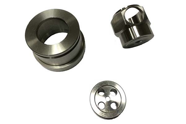
Die casting multi-material defects ruin parts from the inside out. They appear as mottled surfaces, foreign particle inclusions, or excess material flakes —signs that material distribution went wrong during casting. These defects don’t just hurt appearance. They reduce mechanical strength by 15-20% and drive scrap rates to 8-12% for high-precision parts.
What Are the Types of Die Casting Multi-Material Defects?
| Defect Type | Key Features | Typical Locations | Harm Level |
|---|---|---|---|
| Mottled multi-material | Irregular color bands or spotty patterns; no height difference | Large flat surfaces like automotive covers; near gating systems | 3—affects aesthetics, low structural impact |
| Inclusion-based defects | Hard foreign particles—oxide slag, heterogeneous metals—embedded; visible under magnification | Thick-walled areas like engine brackets; runner connections | 5—causes stress concentration, leads to cracking under load |
| Excess material flakes | Thin sheet-like residues on part edges or mold gaps; easy to peel | Sliding mating surfaces like valve bodies; inlay seams | 4—changes part dimensions, disrupts assembly |
| Phase-separated defects | Clear boundaries between material phases—aluminum-zinc segregation; detected via X-ray | Multi-alloy castings like hybrid connectors; near cooling channels | 5—severely reduces tensile strength, unsafe for load-bearing parts |
What Causes Die Casting Multi-Material Defects?
Process parameter imbalances (most common)
Injection speed fluctuations: Speed deviations over ±5m/s —like 30m/s to 36m/s—cause metal front to split, trapping air or oxide films and forming mottled defects.
Specific pressure overload: Pressure over 80MPa for aluminum alloys leads to inertial impact—excess metal squeezes into mold gaps, creating flake residues.
Temperature mismatch: Alloy temperature fluctuations over ±15°C —680°C to 705°C—cause premature solidification of some metal streams, forcing unsolidified material to pile up as excess.
Mold design and maintenance failures
| Mold Problem | Technical Details | Impact |
|---|---|---|
| Unreasonable gating layout | Inner gate offset >2mm from cavity center; sudden cross-section changes from 10mm² to 25mm² | Metal flows to low-resistance areas, causing local overfilling and excess material |
| Insufficient exhaust | Exhaust groove depth <0.2mm or blocked by carbon buildup | Gas cannot escape; metal squeezed to form air pockets and inclusion traps |
| Excessive mold gaps | Sliding mating surface clearance >0.05mm; inlay seam width >0.03mm | Molten metal penetrates gaps, cures into flake residues, changes cavity dimensions |
| Poor surface condition | Mold cavity roughness Ra >1.6μm; residual oxide buildup >0.1mm thick | Metal flow hindered; foreign matter adheres to part surface, forming inclusions |
Material quality and preparation issues
Alloy component deviations: Iron content over 1.2% or zinc over 0.5% in aluminum alloys reduces fluidity by 20-25%, leading to stagnation and phase separation.
Raw material contamination: Charges mixed with over 0.3% heterogeneous metals—copper in aluminum—create phase-separated bands. Metals melt at different temperatures, segregating during cooling.
Inadequate preheating: Metal ingots heated from room temperature directly to melting point cause local cooling rates to differ by 30-40%, inducing mottled defects.
Return material mismanagement: Repeatedly remelted old materials with oxide slag over 0.8% block flow channels and embed slag as inclusions.
Product design flaws
Excessive wall thickness difference: Thickness ratio over 3:1 —6mm vs 2mm—causes uneven cooling. Thick areas solidify slowly, attracting excess metal from thin areas.
Sharp corners and sudden changes: Unrounded corners under 1mm radius create flow dead zones. Metal stagnates, mixing with subsequent streams to form mottled defects.
Operational errors
Inaccurate injection phasing: Starting pressure over 10MPa higher than set value, or pressurization delayed over 0.1s, breaks filling balance and causes local overfilling.
Premature mold opening: Mold opened under 5s before full solidification for aluminum leads to unsolidified metal flowing out, forming flash-like excess material.
Lack of monitoring and maintenance
No digital monitoring: Absence of sensors for injection curves or mold temperature means abnormal fluctuations like ±20°C spikes go undetected until defects appear.
Irregular mold maintenance: Molds not cleaned for over 500 cycles accumulate oxide buildup. Worn cores with dimensional deviation over 0.1mm create uneven cavities that trap foreign matter.
| Cause Category | Primary Issues | Share |
|---|---|---|
| Process | Speed fluctuations, pressure overload, temp mismatch | Most common |
| Mold | Poor gating, insufficient exhaust, gaps, rough surface | High |
| Material | Alloy deviations, contamination, poor preheating | Significant |
| Design | Wall thickness ratio >3:1, sharp corners | Moderate |
| Operation | Wrong phasing, premature opening | Moderate |
| Monitoring | No sensors, irregular maintenance | Contributing |
How Do You Diagnose Multi-Material Defects?
| Diagnosis Tool | Key Functions | Best For Detecting |
|---|---|---|
| High-speed camera (10,000fps) | Tracks metal flow during filling; captures splitting or stagnation | Mottled defects; excess material from uneven flow |
| X-ray flaw detector | Visualizes internal phase separation or inclusions | Phase-separated defects; oxide slag inclusions |
| Infrared thermal imager | Maps mold temperature distribution; detects hot/cold spots | Defects from temperature imbalance—mottling near cold cores |
| Spectrometer | Analyzes alloy composition; identifies heterogeneous metals | Inclusion-based defects; phase separation from contaminated raw materials |
How Do You Fix Each Defect Type?
Fixing mottled multi-material defects
Process optimization:
- Stabilize injection speed with fluctuation ≤ ±2m/s using closed-loop control
- Adjust alloy temperature to 680-700°C for aluminum with precision heater at ±5°C tolerance
Mold upgrade:
- Add diversion ribs at angle ≤ 10° to guide uniform flow; avoid sudden cross-sectional changes in runners
- Install gradient cooling channels with temperature difference ≤ 10°C across mold to eliminate hot spots
Eliminating inclusion-based defects
Material control:
- Enforce alloy composition standards: Fe ≤ 0.9%, Zn ≤ 0.3%, impurities ≤ 0.2% for aluminum
- Use 3-stage degassing: rotary blowing at 400rpm → graphite rotor filtration → online slag removal—removes 95% of oxide slag
Mold maintenance:
- Clean mold cavities with plasma treatment every 300 cycles —removes residual oxide
- Replace worn cores with dimensional deviation > 0.08mm to prevent inclusion traps
Resolving excess material flakes
Mold sealing:
- Reduce sliding mating surface clearance to ≤ 0.03mm via laser cladding; seal inlay seams with high-temperature gaskets
- Polish mold cavity surfaces to Ra ≤0.8μm —reduces metal adhesion and flake formation
Process adjustment:
- Lower specific pressure to 60-70MPa for aluminum to avoid over-squeezing metal into gaps
- Extend mold opening time by 2-3s to ensure full solidification
Addressing phase-separated defects
Material preparation:
- Avoid mixing heterogeneous metals; use single-alloy charges with purity > 99.7%
- Preheat metal ingots to 300-400°C for 2-hour hold before melting to ensure uniform heating
Design modification:
- Reduce wall thickness ratio to ≤ 2:1; add rounded corners at radius ≥ 2mm to eliminate flow dead zones
| Defect Type | Primary Fixes |
|---|---|
| Mottled | Stabilize speed ±2m/s, 680-700°C temp, diversion ribs, gradient cooling |
| Inclusion-based | Alloy specs Fe ≤0.9%, 3-stage degassing, plasma cleaning every 300 cycles |
| Excess flakes | Gap ≤0.03mm, polish to Ra ≤0.8μm, pressure 60-70MPa, +2-3s open time |
| Phase-separated | Single-alloy >99.7% purity, preheat 300-400°C, thickness ratio ≤2:1 |
What Long-Term Prevention Strategies Work?
Digital monitoring system
Install real-time sensors tracking parameters 24/7:
Injection curve monitor: Alerts if speed fluctuations exceed ±3m/s or pressure exceeds ±5MPa
Mold temperature sensors: Maintains variation ≤ ±8°C; triggers alarms for hot or cold spots
Slag detection sensor: Identifies oxide slag > 0.5% in molten metal; stops casting automatically
Standardized maintenance protocol
Mold health check:
- Inspect gating systems and exhaust grooves every 200 cycles; clean carbon buildup with ultrasonic cleaning
- Calibrate mold dimensions with laser interferometer at accuracy ±0.005mm monthly
Material management:
- Label return materials with remelting times—max 3 remelts; test alloy composition before each batch
- Store raw materials in sealed containers to prevent contamination
Operator training and SOP compliance
Train operators to:
- Set injection parameters per part design—0.3m/s initial speed for thin-walled parts
- Conduct first-article inspections for mottling, inclusions before full production
- Enforce 12 mandatory checkpoints —mold temperature, alloy purity—at start of each shift
| Prevention Strategy | Key Actions |
|---|---|
| Digital monitoring | Injection curve, mold temp, slag detection |
| Maintenance | Inspect every 200 cycles, monthly calibration |
| Training | Parameter setting, first-article inspection, 12 checkpoints |
How to write a spec that gets priced correctly
A drawing is a contract. If it leaves a number open, the shop fills that number in with its own default. The default is rarely the one you had in mind. Put these five lines on every RFQ and most of the back-and-forth disappears before it starts.
- 3D model with the parting line marked
- Alloy grade and the standard it meets
- Wall thickness and draft on every face
- Machining allowance on the faces that will be cut
- Pressure tightness or porosity class
The point is not paperwork. Each line removes a decision the shop would otherwise make for you. A complete RFQ comes back priced. An incomplete one comes back guessed.
What actually drives the price
Buyers usually push on material because it is the line they can see. In practice the material is rarely the biggest number on a quote. These five lines decide most of it:
- die steel and cavity count
- part weight and wall section
- draft and slide count
- porosity requirement
- machining allowance
Ask for the quote split by line. A supplier who cannot break it down is guessing, and you will pay for the guess. The line you can usually renegotiate is the tolerance band, not the raw material.
Problems you will meet, and the fix
Every process has a failure mode it prefers. The same four show up again and again on this kind of work, and none of them are mysteries once you know what to look for.
- Cold shuts where two flow fronts meet
- Porosity that shows up only after machining
- Soldering on a hot spot in the die
- Shrinkage voids in a heavy section
Catch the fault on the first part, not the hundredth. A first-article check costs an hour. A bad batch costs the whole order. Write the check into the purchase order so nobody has to remember it.
What to check on the first article
The first article is the cheapest inspection you will ever buy. Use it properly and the rest of the run becomes boring, which is exactly what you want.
- Every dimension on the drawing, with the measured value written beside it.
- The material certificate, matched to the heat or lot number on the parts.
- The finish against the sample you approved, under the same light.
- Fit against the mating part, assembled rather than measured.
- Packaging, because parts that arrive damaged were never in tolerance.
Check in this order: datums, then mating features, then cosmetic faces. If the datums are wrong, every number after them is noise. Keep the report on file. When a problem shows up in month six, that document is the only thing that tells you what changed.
How to compare two quotes fairly
Two numbers are not comparable unless the scope matches. Line them up before you decide, because a low number with three gaps is not a low number.
Same drawing, same material, same finish, same inspection. Anything else is a different job wearing the same part number. Then look at what each quote leaves out. Freight, packaging, certificates and tooling are the usual gaps.
Ask each supplier to state their assumptions in writing. The one who does is usually the one who has run the process before.
Scaling from one part to a batch
The first part teaches you the process. The hundredth teaches you the process cost.
Watch three things as volume grows: setup amortisation, tool wear, and how much hand work the finish still needs. If the unit price barely moves between ten and a hundred, the cost sits in material or in hand work, not in setup. Ask which, because only one of them is negotiable.
Lead time behaves the same way. A one-off is scheduled around other jobs. A repeat order is scheduled around your forecast. Give the shop a forecast and the lead time gets shorter, not longer.
How to read a supplier's quote
A quote is a short document with a long shadow. Four things in it decide whether the job runs smoothly, and only one of them is the price.
- The scope line. It should name the process, the material and the finish, not just the part.
- The tolerance basis. General tolerance or the drawing, and which standard it follows.
- The exclusions. Tooling, freight, certificates and inspection are the usual omissions.
- The validity date. Material prices move, and an open-ended quote is a promise nobody can keep.
Read the exclusions before you read the total. A quote that leaves out tooling is not cheaper. It is a quote for a different job.
What to send with the first order
The first order sets the pattern for every order after it. Send a complete package once and the shop files it, and the second order takes a fraction of the time.
- A STEP or native model plus a PDF drawing carrying the same revision letter.
- The material callout by standard number, not by trade name.
- The finish and the exact faces it applies to.
- Any test the part must pass: fit, seal, drop, salt spray, dielectric.
- A contact who can answer a question inside one working day.
Then write down what was agreed. An email that confirms the material, the finish and the date is worth more than a longer purchase order that leaves them open.
Industry Experience: Multi-Material Defects in Action
An automotive supplier produced engine brackets with 11% multi-material defects—mottled surfaces and inclusions. X-ray showed oxide slag from return material reused 5 times. Solution: 3-stage degassing, limit remelts to 3 times, and plasma clean molds every 300 cycles. Defect rate dropped to 2% in 3 months.
A medical device manufacturer needed sensor housings with zero phase-separated defects. Initial runs had aluminum-zinc segregation from contaminated ingots. Fix: single-alloy charges at 99.8% purity, preheat to 350°C for 2 hours. Phase separation eliminated.
An electronics maker produced heat sinks with excess material flakes on edges. Cause: mold gaps at 0.07mm —over spec. Fix: laser cladding to reduce clearance to 0.03mm, polish to Ra 0.8μm. Flakes gone.
Die casting multi-material defects are preventable with systematic diagnosis and targeted fixes. They come in four types—mottled, inclusion-based, excess flakes, phase-separated—each with different harm levels and root causes. Causes span six dimensions: process parameter imbalances like speed fluctuations over ±5m/s; mold design failures like gaps over 0.05mm; material quality issues like alloy deviations over 0.3%; design flaws like thickness ratios over 3:1; operational errors like premature mold opening; and lack of monitoring. Solutions target each defect type—stabilizing speed to ±2m/s for mottled, 3-stage degassing for inclusions, sealing gaps to 0.03mm for flakes, and single-alloy purity over 99.7% for phase separation. Long-term prevention requires digital monitoring, standardized maintenance, and operator training. With these measures, multi-material defect rates can drop from double digits to under 2%.
Our solution for Die Casting Multi-Material Defects
YiguProto runs die casting in house, from a single prototype to a production batch. We quote the process, the material and the finish as separate lines, so you can see where the money goes instead of arguing with one number.
Send a STEP file or a drawing and you get a DFM report in one to two business days. It flags the features that add cost and the features that will not hold tolerance on the process you picked.
Every order ships with an inspection report on the features you call out. If a part misses, we make it again. Ready to price a part? Start with a free quote and DFM review, or read more about our die casting. You can also talk to an engineer before you commit to a drawing.
FAQ about Die Casting Multi-Material Defects
How long does a first article take?
Usually a few business days once the drawing is frozen, and longer if tooling is involved. The date we give you is the date we confirm in writing, not the date we hope for.
What tolerance can you hold on Die Casting Multi-Material Defects?
The working default is ±0.1 mm on cast features, ±0.05 mm after machining. Tighter than that the process changes and so does the price, because every step tighter adds inspection time. Call out only the faces that mate with something else and leave the rest on the general tolerance.
What should I check before approving the parts?
Datums first, then the features that mate, then the cosmetic faces. Ask for a dimensional report, a material certificate and a finish sample. A part can be inside every tolerance and still not fit, so assemble one before you sign.
What is Die Casting Multi-Material Defects used for?
Die Casting Multi-Material Defects turns up wherever the part has to do a real job at a predictable cost: brackets, housings, fixtures, covers and the fittings that hold them together. The honest test is whether the properties match the load and the environment, not whether the material is fashionable.
How much does Die Casting Multi-Material Defects cost?
Price comes from five lines: material, machine or tool time, setup, finishing and inspection. The material itself is usually the smallest of them. Send a drawing and we will split the quote so you can see which line is doing the damage.
What is the lead time for Die Casting Multi-Material Defects?
Expect 20 to 30 business days including die build. Tooling, material stock and the finishing queue all move that number, so we confirm the date in writing before the run starts rather than after.
The short version
Die Casting Multi-Material Defects rewards the buyer who reads the data sheet and the drawing together. Pick the option for the property that matters, not for the price per kilo.
Tighten only what mates. Test a sample before the run. Then let the process do the rest.