
Rapid Prototyping
Why Are Metal Instrument Prototype Models Critical for Precision Products?
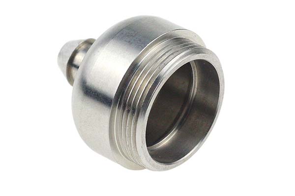
Whether you are a product engineer testing a new sensor design or a procurement specialist sourcing prototypes for medical devices, metal instrument prototype models are essential for turning ideas into viable products. They let you validate designs, test functionality under real conditions, and avoid costly mistakes before committing to mass production.
Key takeaways
- The metal you select directly impacts your prototype’s performance, cost, and how easily it can be machined.
- A strong design phase prevents costly rework later. Two steps are non-negotiable here.
- Once your design is finalized, it is time to turn digital models into physical parts. This phase demands precision and careful testing.
- After machining, your prototype needs finishing work to meet functional and aesthetic goals.
How Do You Choose the Right Metal for Your Prototype?
The metal you select directly impacts your prototype’s performance, cost, and how easily it can be machined. Different applications demand different material properties.
Common Metals for Instrument Prototypes
Here is a detailed comparison of the most popular options:
| Metal Type | Key Properties | Typical Use Cases | Cost Range (USD/lb) | Machinability (1-10) |
|---|---|---|---|---|
| Aluminum Alloy (6061) | Low density, high strength-to-weight ratio, good corrosion resistance | Consumer electronics, light industrial meters, portable instruments | $2.50 – $4.00 | 9 |
| Stainless Steel (304/316) | Excellent corrosion resistance, high-temperature stability, strong | Medical instruments, load-bearing parts, surgical tools | $3.00 – $6.50 | 5 |
| Titanium Alloy (Grade 5) | Ultra-high strength, biocompatibility, heat resistant | Aerospace sensors, high-end medical implants, military equipment | $30.00 – $50.00 | 3 |
Real-World Material Selection Example
A team developing a portable environmental monitor needed a prototype that was both lightweight and durable. They chose 6061 aluminum alloy for several reasons:
- Weight savings: At 2.7 g/cm³, aluminum is about one-third the density of stainless steel
- Machinability: Aluminum cuts easily, reducing production time
- Cost effectiveness: At $2.50–$4.00 per pound, it fit their budget for multiple design iterations
The result: their aluminum prototype was light enough to carry comfortably, and its high machinability cut production time by 30% compared to what stainless steel would have required. They completed three design iterations in the time one stainless steel version would have taken.
When to Choose Each Metal
Aluminum is your best choice when weight matters and you need good corrosion resistance. It works well for handheld instruments, enclosures, and parts that don’t face extreme stress.
Stainless steel is ideal for medical instruments, food-contact equipment, or any application requiring sterilization or exposure to harsh chemicals. It maintains integrity at temperatures up to 800°C and resists corrosion from most acids and cleaners.
Titanium is necessary for aerospace components, implantable medical devices, or any part requiring the absolute highest strength-to-weight ratio. It is biocompatible, meaning it can contact human tissue without reaction, and maintains strength at temperatures that would soften aluminum.
What Goes Into the Design Phase for Metal Prototypes?
A strong design phase prevents costly rework later. Two steps are non-negotiable here.
Creating Precise 3D Models
Use professional CAD software like SolidWorks, UG NX, or Catia to create detailed 3D models of your instrument. These models must include every feature—from the shape of external casings to the exact location of mounting holes and internal cavities.
For complex geometries: Catia excels at capturing intricate shapes like curved sensor housings or ergonomic handles. An automotive sensor manufacturer added tolerance labels to their Catia model—every critical dimension specified with allowable deviation. This simple step reduced prototype errors by 40% because machinists knew exactly what mattered.
Critical details to include:
- Wall thicknesses throughout the part
- Hole sizes and locations with tolerances
- Thread specifications for any tapped holes
- Surface finish requirements for functional areas
- Assembly interfaces and mating surfaces
Performing Design Analysis Before Machining
Before cutting any metal, test your design with simulation software. These tools analyze stress distribution, thermal deformation, and dynamic behavior to spot issues early.
Case study: An industrial thermometer team used simulation software to check how their prototype would perform in high-temperature environments up to 200°C. The analysis revealed a weak spot in the housing where thermal expansion would cause warping, potentially jamming the internal mechanism. They reinforced the area in the CAD model before any metal was cut, saving an estimated $2,000 in rework costs and 2 weeks of development time.
What simulation can catch:
- Stress concentrations that could lead to failure
- Thermal expansion issues in multi-material assemblies
- Vibration modes that might affect sensitive instruments
- Interference between moving parts
How Do You Program and Machine Metal Prototypes?
Once your design is finalized, it is time to turn digital models into physical parts. This phase demands precision and careful testing.
CAM Programming: Converting Design to Machine Code
CAM software like Mastercam or SolidCam converts your 3D model into code that CNC machines can read. The software generates tool paths—step-by-step instructions for the machine’s cutting tools.
Why it matters: A well-written CAM program improves both efficiency and quality. A medical device maker used SolidCam to optimize tool paths for a prototype with tiny components—some features as small as 0.5 mm. By programming efficient cutting strategies, they reduced machining time from 8 hours to 5 hours per part, a 37% improvement.
Key programming considerations for metals:
- Feed rates: Aluminum cuts well at higher speeds; stainless steel and titanium need slower, controlled feeds
- Tool selection: Different materials require specific tool geometries and coatings
- Coolant strategy: Metals generate heat; proper coolant application prevents work hardening and tool wear
Testing the Program Before Cutting
Never skip program simulation. Use tools like Vericut to test your CNC program for errors or collisions before any metal is cut. Simulation reveals:
- Tool collisions with the machine or workpiece
- Inefficient tool paths that waste time
- Areas where the tool cannot reach as intended
- Potential chatter or vibration issues
A manufacturer who skipped this step learned the hard way—their tool crashed into the part during the first cut, destroying a $500 piece of stainless steel and wasting 8 hours of machine time.
CNC Machining: Choosing the Right Equipment
Select your CNC machine based on part complexity:
| Machine Type | Best For | Typical Accuracy | Advantages |
|---|---|---|---|
| 3-axis | Simple parts with features on one side—flat panels, basic housings | ±0.05 mm | Cost-effective, fast setup, good for 2D contours |
| 4-axis | Parts requiring rotation for angled features or multiple sides | ±0.03 mm | Reduces setups, better for cylindrical features |
| 5-axis | Complex parts with undercuts, curved surfaces, or angled ports | ±0.02 mm | Machines complex shapes in one setup, best surface finish |
Data point: 5-axis machining achieves tolerances as tight as ±0.001 inches (0.025 mm)—critical for instruments requiring high measurement accuracy like laboratory scales or precision sensors.
What Post-Processing Steps Enhance Metal Prototypes?
After machining, your prototype needs finishing work to meet functional and aesthetic goals.
Essential Surface Treatments
Deburring: Remove sharp edges and tool marks. This is especially important for instruments that will be handled or assembled with other components. A burr left on a medical instrument could cut through gloves or irritate tissue.
Sandblasting: Creates a uniform matte finish that improves grip on handheld instruments and hides minor surface imperfections. It also prepares surfaces for painting or coating.
Anodizing (for aluminum): Adds a protective oxide layer that boosts corrosion resistance by 50% or more. The anodized layer is hard, durable, and can be dyed in various colors. A marine instrument manufacturer anodized their aluminum prototype to withstand saltwater exposure. The treated prototype lasted 3 times longer in accelerated corrosion testing compared to an uncoated version.
Passivation (for stainless steel): Removes free iron from the surface, enhancing corrosion resistance. This is essential for medical instruments that will be sterilized repeatedly.
Plating: Adds a thin layer of another metal—like nickel or chrome—for improved wear resistance, conductivity, or appearance.
Assembly and Functional Testing
Assemble all parts into a complete prototype, then run tests that verify:
- Measurement accuracy: Does the instrument give correct readings across its operating range?
- Stability: Does performance remain consistent over time and through multiple use cycles?
- Environmental adaptability: Can it handle humidity, temperature changes, or vibration?
- User interaction: Is it comfortable to hold and operate?
For medical instruments: Add biocompatibility testing to ensure the prototype is safe for human contact. This may include cytotoxicity tests, skin irritation studies, or material certification reviews.
What Quality Control Measures Ensure Reliable Prototypes?
Quality control keeps your prototype reliable and representative of what production will deliver.
Multi-Stage Inspection
Set up checkpoints at every stage:
| Stage | What to Check | Tools to Use |
|---|---|---|
| Raw material | Material certification, surface defects | Visual, certificate review |
| After roughing | Critical dimensions, stock remaining | Calipers, CMM |
| After finishing | All dimensions, surface finish | CMM, surface roughness tester, optical comparator |
| After post-processing | Coating quality, cosmetic appearance | Visual, adhesion tests, thickness gauges |
| Final assembly | Fit, function, movement | Functional testing fixtures |
If any part is substandard—like a hole that is too small or a surface finish that is too rough—rework or remake it immediately. Do not assume it will “work well enough.”
ISO Certification and Traceability
Follow ISO 9001 standards for quality management. This ensures:
- Consistent processes across all prototypes
- Traceability—you can track every step from raw material batch to final inspector
- Documentation of all inspections and tests
- Corrective action when issues arise
Statistic: Companies using ISO 9001 for prototype machining reduce defect rates by an average of 25%, according to a 2024 manufacturing industry report. The documentation alone helps catch recurring issues before they become expensive problems.
How to write a spec that gets priced correctly
A drawing is a contract. If it leaves a number open, the shop fills that number in with its own default. The default is rarely the one you had in mind. Put these five lines on every RFQ and most of the back-and-forth disappears before it starts.
- A model you are willing to freeze for the build
- The question the prototype must answer
- Process and material that can answer it
- Tolerance on the features under test
- How many iterations you have budgeted
The point is not paperwork. Each line removes a decision the shop would otherwise make for you. A complete RFQ comes back priced. An incomplete one comes back guessed.
What actually drives the price
Buyers usually push on material because it is the line they can see. In practice the material is rarely the biggest number on a quote. These five lines decide most of it:
- process choice
- part size and feature count
- material
- finish and fit checks
- number of iterations
Ask for the quote split by line. A supplier who cannot break it down is guessing, and you will pay for the guess. The line you can usually renegotiate is the tolerance band, not the raw material.
Problems you will meet, and the fix
Every process has a failure mode it prefers. The same four show up again and again on this kind of work, and none of them are mysteries once you know what to look for.
- A prototype that is too good and hides a production problem
- A prototype that is too rough to test the real question
- Material chosen for speed rather than for the test
- No measurement plan, so the result is an opinion
Catch the fault on the first part, not the hundredth. A first-article check costs an hour. A bad batch costs the whole order. Write the check into the purchase order so nobody has to remember it.
What to check on the first article
The first article is the cheapest inspection you will ever buy. Use it properly and the rest of the run becomes boring, which is exactly what you want.
- Every dimension on the drawing, with the measured value written beside it.
- The material certificate, matched to the heat or lot number on the parts.
- The finish against the sample you approved, under the same light.
- Fit against the mating part, assembled rather than measured.
- Packaging, because parts that arrive damaged were never in tolerance.
Check in this order: datums, then mating features, then cosmetic faces. If the datums are wrong, every number after them is noise. Keep the report on file. When a problem shows up in month six, that document is the only thing that tells you what changed.
How to compare two quotes fairly
Two numbers are not comparable unless the scope matches. Line them up before you decide, because a low number with three gaps is not a low number.
Same drawing, same material, same finish, same inspection. Anything else is a different job wearing the same part number. Then look at what each quote leaves out. Freight, packaging, certificates and tooling are the usual gaps.
Ask each supplier to state their assumptions in writing. The one who does is usually the one who has run the process before.
What Real Problems Does Metal Prototyping Solve?
Here are three cases showing how proper metal prototyping prevented major issues.
Case 1: The Surgical Tool That Slipped
A medical device company designed a new surgical forceps. Their first stainless steel prototype looked good but during testing, surgeons reported it slipped when gripping wet tissue. Analysis showed the surface was too smooth. They added a light texture to the gripping surface via secondary machining, tested again, and received positive feedback. Fixing this before production saved a recall that would have affected 10,000 instruments.
Case 2: The Sensor That Drifted With Temperature
An industrial sensor manufacturer tested aluminum prototypes and found measurement drift at high temperatures. Investigation revealed the aluminum housing expanded enough at 150°C to slightly shift internal components. They switched to a stainless steel prototype with lower thermal expansion, retested, and the drift disappeared. The material change added $8 to the part cost but prevented field failures that would have cost $50,000 in warranty claims.
Case 3: The Aerospace Component That Weighed Too Much
An aerospace supplier designed a mounting bracket for a critical sensor. Their first stainless steel prototype weighed 1.8 kg—too heavy for the application. They switched to titanium alloy, machined a new prototype weighing 1.1 kg, and maintained all strength requirements. The titanium prototype passed flight qualification tests, and the weight savings allowed the aircraft to carry additional fuel.
Metal instrument prototype models transform digital designs into physical parts you can test, validate, and refine. Starting with careful material selection—aluminum for lightweight applications, stainless steel for corrosion resistance, titanium for extreme strength—and progressing through precise design, advanced machining, thorough post-processing, and rigorous quality control, each step builds confidence that your final product will perform as intended. Real cases show that companies investing time in proper metal prototyping avoid expensive field failures, accelerate development, and create instruments that meet demanding real-world requirements.
Our solution for Metal Instrument Prototype Models Critical
YiguProto runs rapid prototyping in house, from a single prototype to a production batch. We quote the process, the material and the finish as separate lines, so you can see where the money goes instead of arguing with one number.
Send a STEP file or a drawing and you get a DFM report in one to two business days. It flags the features that add cost and the features that will not hold tolerance on the process you picked.
Every order ships with an inspection report on the features you call out. If a part misses, we make it again. Ready to price a part? Start with a free quote and DFM review, or read more about our rapid prototyping. You can also talk to an engineer before you commit to a drawing.
FAQ about Metal Instrument Prototype Models Critical
How long does a first article take?
Usually a few business days once the drawing is frozen, and longer if tooling is involved. The date we give you is the date we confirm in writing, not the date we hope for.
How much does Metal Instrument Prototype Models Critical cost?
Price comes from five lines: material, machine or tool time, setup, finishing and inspection. The material itself is usually the smallest of them. Send a drawing and we will split the quote so you can see which line is doing the damage.
What should I check before approving the parts?
Datums first, then the features that mate, then the cosmetic faces. Ask for a dimensional report, a material certificate and a finish sample. A part can be inside every tolerance and still not fit, so assemble one before you sign.
What is Metal Instrument Prototype Models Critical used for?
Metal Instrument Prototype Models Critical turns up wherever the part has to do a real job at a predictable cost: brackets, housings, fixtures, covers and the fittings that hold them together. The honest test is whether the properties match the load and the environment, not whether the material is fashionable.
What is the lead time for Metal Instrument Prototype Models Critical?
Expect 3 to 7 business days for a first article. Tooling, material stock and the finishing queue all move that number, so we confirm the date in writing before the run starts rather than after.
How do I compare two quotes fairly?
Match the scope first: same drawing, same material, same finish, same inspection. Then read the exclusions. Freight, tooling and certificates are the usual gaps, and a low number with three gaps is not a low number.
The short version
Metal Instrument Prototype Models Critical rewards the buyer who reads the data sheet and the drawing together. Pick the option for the property that matters, not for the price per kilo.
Tighten only what mates. Test a sample before the run. Then let the process do the rest.