
Rapid Prototyping
Why Is the Metal Robot Prototype Model Essential for Reliable Robotics?
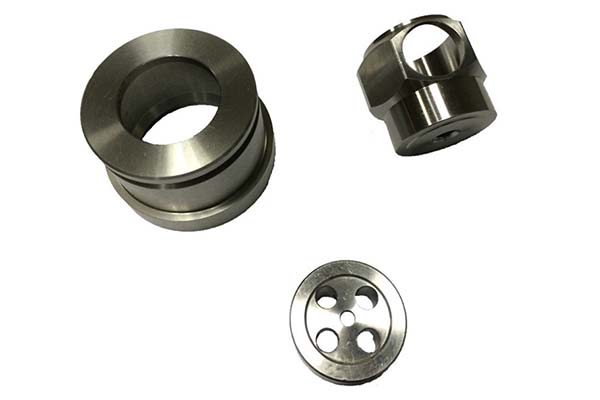
If you are a procurement specialist or product engineer working in robotics, mastering the metal robot prototype model process is key to turning design ideas into functional, reliable machines. Metal prototypes let you test durability, movement, and structural stability under real-world conditions—critical for avoiding costly mistakes when you move to mass production.
Key takeaways
- Selecting the correct metal is the first major decision in building a metal robot prototype.
- You cannot build a good prototype without clear, accurate data. This stage ensures your final part matches your design exactly.
- CNC machining is the heart of metal robot prototype manufacturing. It delivers the precision and repeatability that robotic applications demand.
- Robots need to last and look good. Surface treatment accomplishes both goals.
How Do You Choose the Right Metal for Your Robot Prototype?
Selecting the correct metal is the first major decision in building a metal robot prototype. Robots need materials that balance strength, weight, and cost. Here is how to choose wisely based on your specific application.
Common Metals for Robot Prototypes
| Metal Type | Key Properties | Ideal Robot Components | Real-World Example | Cost Range (USD/lb) |
|---|---|---|---|---|
| Aluminum Alloy (6061) | Low density (2.7 g/cm³), easy to machine, good strength | Arm joints, lightweight frames, structural components | A factory robot maker used 6061 aluminum for arm prototypes—cut weight by 35% vs. steel, improving movement speed and reducing motor load | $2–$5 |
| Stainless Steel (304/316) | Corrosion-resistant, high strength, heat tolerant | Grippers, outdoor robot bodies, medical robots | A warehouse robot prototype used 316 stainless steel for grippers handling wet packages—no rust after 8 months of continuous use | $3–$8 |
| Brass | Good electrical conductivity, easy to machine, attractive finish | Sensor mounts, electrical connectors, decorative accents | A service robot team used brass for sensor prototypes—ensured stable signal transmission during testing with minimal interference | $8–$12 |
| Magnesium Alloy | Ultra-light (1.8 g/cm³), high rigidity, good damping | Small robot frames, drone components, portable robots | A medical robot prototype used magnesium alloy for its body—weighed 20% less than aluminum, ideal for tight spaces and weight-sensitive applications | $10–$15 |
| Zinc Alloy | Low cost, good castability, decent strength | Decorative covers, simple housings, non-structural parts | A toy robot company used zinc alloy for prototype covers—saved 40% on material costs compared to aluminum while maintaining appearance | $1.5–$4 |
Material Selection Tips for Different Robot Types
For robots that move frequently, like factory arms or collaborative robots, aluminum alloy offers the best balance of light weight, strength, and machinability. A logistics robot developer chose 6061 aluminum for a six-axis arm prototype. The weight savings allowed them to use smaller, cheaper motors while maintaining speed and precision.
For outdoor robots facing rain, humidity, or chemicals, stainless steel is essential. An agricultural robot company learned this when their aluminum prototype corroded after just 3 weeks in a greenhouse environment. Switching to 316 stainless steel for the next prototype eliminated corrosion issues.
For weight-critical applications like drones or small medical robots, magnesium alloy delivers maximum weight savings. A surgical robot team reduced their prototype’s weight by 20% by switching from aluminum to magnesium, making it easier for surgeons to maneuver.
For budget-conscious projects, zinc alloy works well for non-structural parts like covers and enclosures. A consumer robot startup used zinc for their prototype’s outer shell, saving thousands while still achieving the look and feel they needed for user testing.
What Data Collection Ensures Prototype Accuracy?
You cannot build a good prototype without clear, accurate data. This stage ensures your final part matches your design exactly.
Importing and Verifying 3D CAD Files
Start with 3D drawings or CAD files from your design team—these are the master blueprint. Common tools include:
- AutoCAD for 2D drawings and simple parts
- SolidWorks for detailed 3D models with assemblies
- Fusion 360 for collaborative teams and iterative design
Critical check: Always verify file details before machining. A robot startup once skipped this step—their prototype’s arm joint was 1 mm too small because the CAD file dimension was misread. The part could not move smoothly, causing a 2-week delay while they remachined.
What to verify in CAD files:
- All dimensions match the design intent
- Tolerances are specified for critical features
- Hole locations and sizes are correct
- Thread specifications are included where needed
- Assembly interfaces are clearly defined
Creating Initial Concept Prototypes
Before committing to expensive metal machining, consider creating simple prototypes to test basic fit and function. Two common methods:
SLA laser rapid prototyping: Fast (1–2 days) for small, detailed parts like sensor brackets or connector housings. These plastic prototypes let you verify fit and clearance before cutting metal.
CNC machining in plastic: For larger parts, machining in ABS or other plastics can validate geometry at lower cost than metal.
Case example: A logistics robot team used SLA to make gripper prototypes from photosensitive resin. When they tested the grippers with actual boxes, they discovered the fingers were too narrow to grip securely. They widened the design in CAD before machining any metal, saving thousands in rework costs.
How Does CNC Machining Create Precision Robot Parts?
CNC machining is the heart of metal robot prototype manufacturing. It delivers the precision and repeatability that robotic applications demand.
Programming and Setup
Engineers write code for the CNC machine based on your 3D models. This G-code tells the machine exactly how to cut, drill, and shape the metal.
Key benefits of CNC machining:
- High accuracy: Tolerances as tight as ±0.001 mm for critical features like bearing seats and joint pivots
- Consistent results: Every part is identical, making assembly predictable
- Surface finish: Achieves smooth surfaces down to Ra 0.4 μm where needed
Example: A factory robot maker used CNC programming for 10 arm joint prototypes. Every part matched the CAD model within ±0.02 mm, and all 10 assembled perfectly with no rework needed.
Multi-Axis Machining for Complex Parts
For complex geometries like curved robot bodies or multi-angle joints, choose the right machine:
| Machine Type | Best For | Accuracy | Advantages |
|---|---|---|---|
| 3-axis | Simple parts with features on one side—flat frames, basic brackets | ±0.05 mm | Cost-effective, fast setup, good for 2D contours |
| 4-axis | Parts requiring rotation for angled features or cylindrical components | ±0.03 mm | Reduces setups, better for holes at angles |
| 5-axis | Complex parts with undercuts, curved surfaces, or internal features | ±0.02 mm | Machines complex shapes in one setup, best surface finish |
Statistic: 5-axis machining reduces prototype errors by 50% compared to traditional methods, according to robotics manufacturing data. It also cuts production time by 30% for complex parts by eliminating multiple setups.
What Manual Processing Steps Perfect Metal Parts?
Even precision CNC parts need hands-on finishing to be perfect.
Deburring: Removing Sharp Edges
Use sandpaper, deburring tools, or rotary brushes to smooth sharp edges and knife marks left by machining. This prevents scratches on other components and protects assembly workers.
Why it matters: A robot arm prototype once had a small burr on a mounting flange. During testing, that burr scratched a conveyor belt, leaving marks that damaged products. Deburring would have caught this easy-to-miss issue.
Tools and techniques:
- Hand deburring tools for accessible edges
- Tumbling for small parts with complex geometry
- Ultrasonic cleaning to remove fine metal particles
Grinding and Polishing
Check your drawings for surface finish requirements. Different areas need different treatments:
- Robot joints and bearing surfaces need polished finishes to move smoothly without friction
- External covers and visible parts need grinding to look neat and professional
- Mounting surfaces need flatness for proper alignment
Example: A service robot team polished their prototype’s exterior body to a smooth finish. During user testing, operators commented that the smooth surface was easier to clean than textured alternatives—a valuable insight for production design.
What Surface Treatments Boost Durability and Appearance?
Robots need to last and look good. Surface treatment accomplishes both goals.
Key Surface Processes for Metal Robot Prototypes
| Process | Purpose | Ideal Robot Components |
|---|---|---|
| Painting | Add color, hide surface imperfections, provide corrosion protection | External bodies, covers, aesthetic parts |
| Sandblasting | Create uniform matte finish, improve grip, prepare for painting | Grippers, foot pads, surfaces needing texture |
| Anodizing (aluminum) | Prevent corrosion, add color, increase surface hardness | Arm joints, frames, structural parts |
| Passivation (stainless) | Remove free iron, enhance corrosion resistance | Medical robot parts, food-handling components |
| Laser Engraving | Add permanent logos, labels, or warnings | Control panels, identification plates |
| Silk Screen Printing | Add text or symbols (e.g., “Caution,” “Power”) | Safety covers, buttons, user interfaces |
Case study: An outdoor security robot company used anodizing on aluminum arm prototypes. After 6 months exposed to rain, snow, and temperature swings, there was no corrosion, and the arms moved as smoothly as day one. An uncoated aluminum part would have shown pitting within weeks.
How Do You Assemble and Test the Complete Prototype?
Putting all parts together and validating performance is the final—and most important—step.
Test Assembly: Checking Fit and Function
First, assemble the complete prototype to verify:
- Part fit: Does the arm attach to the body correctly? Do all fasteners engage properly?
- Structural stability: Can the robot hold its own weight plus expected loads without tipping or flexing?
- Clearance: Do moving parts have enough space to operate without interference?
Example: A medical robot team discovered during test assembly that a sensor mount was misaligned by 0.3 mm. They adjusted the mount before functional testing, avoiding a failure that would have shown up as inaccurate readings later.
Functional Testing: Validating Real-World Performance
Test how the prototype performs in conditions that mimic actual use:
Structural stability: Shake the robot or apply vibration to see if any parts loosen. A good design withstands 10,000+ vibration cycles without fastener loosening.
Mechanical performance: Verify that joints move smoothly through their full range of motion. A robot arm should lift its rated load 100+ times without binding or excessive wear.
Simulated use testing: Run the robot in an environment that replicates its intended application. A warehouse robot prototype should move boxes continuously for 8+ hours to identify any fatigue issues.
Case study: A warehouse robot prototype failed simulated use testing—it could not reliably grip wet boxes, dropping 15% during trials. The team added a textured rubber layer to the metal grippers, retested, and achieved a 99% success rate. Fixing this before production saved thousands in potential returns and customer complaints.
What Quality Control Measures Ensure Reliability?
Quality control throughout the process prevents problems from reaching final assembly.
In-Process Inspection
Check parts at multiple stages:
| Stage | What to Check | Tools to Use |
|---|---|---|
| After rough machining | Critical dimensions, stock remaining | Calipers, micrometers |
| After finishing | All dimensions, surface finish | CMM, surface roughness tester |
| After surface treatment | Coating quality, thickness | Visual, thickness gauges, adhesion tests |
| During assembly | Fit, alignment, movement | Feeler gauges, torque wrenches |
Final Validation
Before shipping, verify:
- All dimensions meet specifications
- Surface treatments are uniform and defect-free
- Moving parts operate smoothly
- Documentation is complete (material certs, inspection reports)
How to write a spec that gets priced correctly
A drawing is a contract. If it leaves a number open, the shop fills that number in with its own default. The default is rarely the one you had in mind. Put these five lines on every RFQ and most of the back-and-forth disappears before it starts.
- A model you are willing to freeze for the build
- The question the prototype must answer
- Process and material that can answer it
- Tolerance on the features under test
- How many iterations you have budgeted
The point is not paperwork. Each line removes a decision the shop would otherwise make for you. A complete RFQ comes back priced. An incomplete one comes back guessed.
What actually drives the price
Buyers usually push on material because it is the line they can see. In practice the material is rarely the biggest number on a quote. These five lines decide most of it:
- process choice
- part size and feature count
- material
- finish and fit checks
- number of iterations
Ask for the quote split by line. A supplier who cannot break it down is guessing, and you will pay for the guess. The line you can usually renegotiate is the tolerance band, not the raw material.
Problems you will meet, and the fix
Every process has a failure mode it prefers. The same four show up again and again on this kind of work, and none of them are mysteries once you know what to look for.
- A prototype that is too good and hides a production problem
- A prototype that is too rough to test the real question
- Material chosen for speed rather than for the test
- No measurement plan, so the result is an opinion
Catch the fault on the first part, not the hundredth. A first-article check costs an hour. A bad batch costs the whole order. Write the check into the purchase order so nobody has to remember it.
What Real Problems Does Metal Robot Prototyping Solve?
Here are three cases showing how proper metal prototyping prevented major issues.
Case 1: The Robot Arm That Flexed Too Much
A factory automation company designed a new heavy-lift robot arm. Their first aluminum prototype revealed unexpected flex during testing—the arm deflected 2 mm at full extension under load, enough to affect positioning accuracy. Analysis showed the wall thickness was insufficient. They increased thickness by 20% in critical areas, machined a new prototype, and verified deflection dropped to 0.5 mm. Fixing this before production saved a recall that would have affected 500 units.
Case 2: The Outdoor Robot That Rusted
A security robot company built their first prototype in standard steel. After just 2 weeks of outdoor testing, visible rust appeared on joints and fasteners. They switched to 316 stainless steel for all exposed components, and the next prototype showed no corrosion after 6 months of continuous outdoor exposure. The material upgrade added 15% to part cost but eliminated a warranty issue that would have cost far more.
Case 3: The Medical Robot With Signal Interference
A surgical robot prototype experienced intermittent sensor errors during testing. Investigation revealed that the aluminum housing was not providing enough electromagnetic shielding. They added a nickel-based conductive coating to the interior surfaces, and the interference disappeared. The fix cost $50 per unit versus a complete redesign that would have taken months.
The metal robot prototype model process transforms digital designs into physical robots you can test, validate, and refine. Starting with careful material selection—aluminum for moving parts, stainless steel for corrosion resistance, magnesium for light weight—and progressing through precise machining, thorough finishing, and realistic testing, each step builds confidence that your final product will perform reliably. Real cases show that companies investing time in proper metal prototyping avoid expensive field failures, accelerate development, and create robots that meet demanding real-world requirements.
Our solution for Metal Robot Prototype Model
YiguProto runs rapid prototyping in house, from a single prototype to a production batch. We quote the process, the material and the finish as separate lines, so you can see where the money goes instead of arguing with one number.
Send a STEP file or a drawing and you get a DFM report in one to two business days. It flags the features that add cost and the features that will not hold tolerance on the process you picked.
Every order ships with an inspection report on the features you call out. If a part misses, we make it again. Ready to price a part? Start with a free quote and DFM review, or read more about our rapid prototyping. You can also talk to an engineer before you commit to a drawing.
FAQ about Metal Robot Prototype Model
Can Metal Robot Prototype Model be made in small quantities?
Yes, and small quantities are where a good supplier earns the next order. Setup dominates the price at low volume, so the cheapest route is usually the one with the fewest operations, not the cheapest material.
How much does Metal Robot Prototype Model cost?
Price comes from five lines: material, machine or tool time, setup, finishing and inspection. The material itself is usually the smallest of them. Send a drawing and we will split the quote so you can see which line is doing the damage.
How long does a first article take?
Usually a few business days once the drawing is frozen, and longer if tooling is involved. The date we give you is the date we confirm in writing, not the date we hope for.
What is Metal Robot Prototype Model used for?
Metal Robot Prototype Model turns up wherever the part has to do a real job at a predictable cost: brackets, housings, fixtures, covers and the fittings that hold them together. The honest test is whether the properties match the load and the environment, not whether the material is fashionable.
What should I check before approving the parts?
Datums first, then the features that mate, then the cosmetic faces. Ask for a dimensional report, a material certificate and a finish sample. A part can be inside every tolerance and still not fit, so assemble one before you sign.
Does the process work for prototypes as well as production?
Yes, and that is usually the point. Running the prototype on the production process removes a whole class of surprises, because the part you test is made the same way as the part you sell.
The short version
Metal Robot Prototype Model rewards the buyer who reads the data sheet and the drawing together. Pick the option for the property that matters, not for the price per kilo.
Tighten only what mates. Test a sample before the run. Then let the process do the rest.