
Sheet Metal
How Fast Can You Prototype with Sheet Metal?
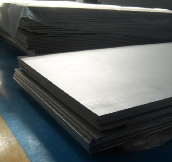
In hardware development, speed isn’t just competitive—it’s essential. The need to go from CAD design to a real, testable part is critical. For engineers and designers working with metal, this need creates a major bottleneck. Quick sheet metal prototyping solves this problem, delivering high-quality metal parts in days instead of months.
What Is Rapid Prototyping with Sheet Metal?
The core concept
Rapid prototype sheet metal refers to manufacturing processes that turn a 3D CAD model into a physical metal part with maximum speed and minimum upfront cost. Unlike traditional mass production that relies on expensive, time-consuming hard tooling like stamping dies, rapid prototyping uses tool-free or soft-tooling techniques. This approach is built specifically for testing a design’s form, fit, and function.
Why it matters
This method is essential for modern product development. It lets engineering teams:
- Hold a real part
- Test assembly fit
- Check mechanical performance
- Make critical design changes
All before committing the six-figure costs and multi-month lead times of production tooling.
Key benefits
Speed: A design finished Monday can often be a real part in your hands by Friday. Impossible with traditional methods.
Cost-effectiveness: For quantities from one piece to several hundred, rapid prototyping is far more affordable. It eliminates the huge upfront cost of dies and molds.
Design iterations: You can quickly make multiple versions, test each, and refine based on real-world feedback. This leads to stronger final products.
Real material: 3D-printed plastic is useful for early shape checks, but it can’t replicate the strength, weight, and thermal properties of metal. Rapid sheet metal prototyping lets you test in actual production material—aluminum, steel, or copper.
What Are the Main Manufacturing Techniques?
Cutting: The first step
The process begins by cutting a 2D flat pattern from a stock sheet. This pattern is digitally unfolded from your 3D model. Two main cutting methods dominate rapid prototyping.
Laser cutting is the workhorse. A high-powered, focused laser beam melts or vaporizes the material, leaving an extremely clean, precise edge. A gas jet (nitrogen or oxygen) clears away melted material. Laser cutting is extremely fast and accurate for stainless steel, aluminum, and carbon steel in thin to medium thicknesses.
Waterjet cutting uses a highly pressurized stream of water mixed with abrasive garnet to erode material. It’s a cold-cutting process—no heat, no heat-affected zone that could alter material properties. Perfect for thick materials (several inches), heat-sensitive alloys, plastics, composites, and materials that produce harmful fumes when lasered.
Forming: Creating 3D shape
Once cut, the flat pattern must be bent into its final 3D shape. This is almost always done with a CNC press brake.
A press brake forms bends by clamping the sheet between a matching punch and die. CNC (Computer Numerical Control) precisely controls the backgauge position and punch stroke depth, allowing highly repeatable bends at exact angles. Key design factors include bend radius (must be appropriate for material thickness to prevent cracking) and K-factor (helps calculate correct flat pattern dimensions).
Assembly and finishing
For multi-part assemblies or specific surface properties, additional steps are needed.
Hardware insertion: Many designs need threaded features. Instead of tapping thin metal (minimal thread engagement), manufacturers press in self-clinching fasteners—nuts, studs, and standoffs.
Welding: When an assembly can’t be formed from one piece, components are joined. TIG welding is preferred for prototypes due to precision and clean appearance. MIG welding is faster and also common.
Finishing: Provides both cosmetic appeal and functional protection. Options include powder coating (durable color), anodizing (corrosion resistance and color for aluminum), and plating (zinc or nickel for corrosion protection and conductivity).
Technique comparison
| Technique | Best For | Speed | Precision | Material Thickness |
|---|---|---|---|---|
| Laser cutting | General purpose, intricate designs | Very fast | High | Thin to medium |
| Waterjet cutting | Thick materials, heat-sensitive alloys | Slower | High | Very thick |
| CNC punching | Standard shapes, louvers, forms | Fast (specific designs) | Good | Thin to medium |
How Fast Is “Quick” Prototyping?
Typical turnaround times
For most standard rapid sheet metal services, expect 3 to 7 business days from order placement to shipping. Many providers offer expedited options for an additional fee, sometimes delivering in 24–48 hours.
Factors that extend timelines
Part complexity: A simple flat plate with a few holes is much faster than a complex chassis with dozens of bends. Each bend requires a separate press brake setup.
Quantity: Producing 50 parts takes more machine time and handling than one part.
Finishing: Post-processing is often the most time-consuming. Powder coating, anodizing, or plating are typically batched and can add 2 to 4 business days for curing or processing.
Provider capacity: Quoted lead times depend on current workload. During peak periods, standard times may stretch. This is why getting quotes from multiple providers helps.
What Tolerances Can You Expect?
Industry standard tolerances
For laser-cut features, typical tolerance is ±0.005 inches (0.13mm). For bends formed on a CNC press brake, standard angular tolerance is ±1 degree. These are sufficient for the vast majority of form, fit, and function prototypes.
Avoid over-tolerancing
If a feature doesn’t functionally require tighter tolerance, don’t specify one. Requesting tighter-than-standard tolerances often requires special handling, additional QC steps, and potentially different machinery—all increasing cost and extending lead time.
Best practice: Only call out critical-to-function dimensions on your 2D drawing. Leave all other features to the provider’s standard tolerance capabilities.
What Design Tips Speed Up Production and Cut Costs?
Based on processing thousands of prototype orders, these principles directly impact manufacturability. Designs following these guidelines see average quote reductions of 15% and often deliver a day faster.
Standardize bend radii
Each unique bend radius may require a different tool loaded into the press brake. Tool changes take time and add cost. Design all bends with a single, consistent inside radius (e.g., 0.030″ or 1.0mm is common). This allows the entire part to be formed in one machine setup.
Respect material thickness
Metal cracks if bent too sharply. Fundamental rule: design bends with inside radius at least equal to material thickness. For 0.060″ (1.5mm) aluminum, minimum inside bend radius should be 0.060″. For harder materials or less bendable alloys, this minimum may be larger. Violating this rule is a top reason designs get rejected or require costly revision.
Keep holes away from bends
When metal bends, material around the bend line deforms. Holes too close get stretched into ovals. Safe rule: maintain distance from hole edge to bend start of at least four times material thickness.
Use standard hole sizes
While lasers cut any hole size, designing with standard hardware and drill bit sizes can reduce costs, especially if providers use punching as a secondary operation. Off-the-shelf fasteners are always cheaper than custom.
Minimize complex geometries
Avoid extremely small or hard-to-access features. Tiny tabs are fragile and difficult to handle. Bends creating deep, narrow channels may be impossible to form because press brake tooling can’t fit inside. Simplify wherever possible without compromising function.
Provide clear documentation
Always supplement your 3D CAD model (universal format like.step) with a clear 2D manufacturing drawing (.pdf). The 3D model defines geometry. The 2D drawing communicates what the model cannot: material type, thickness, finish requirements, hardware specs, and critical-to-function dimensions requiring specific tolerances. This dual-documentation eliminates confusion and prevents costly errors.
How Does Prototyping Cost Compare to Traditional Methods?
Different economic models
Rapid prototyping and traditional mass production (like stamping) have fundamentally different cost structures.
Rapid prototyping cost: Driven primarily by machine time and material usage. Little to no upfront setup cost (NRE). Results in a relatively high but stable cost-per-part, whether you order one or one hundred.
Traditional stamping cost: Defined by massive upfront investment in hard tooling. Creating custom steel dies can cost $10,000 to over $100,000. Once tooling is made, per-part cost is extremely low—often pennies.
The break-even point
This dynamic is best visualized as a cost-per-part versus quantity graph. Rapid prototyping line is nearly flat at moderate cost. Stamping line starts astronomically high for one part (entire tooling cost) then drops steeply, eventually crossing below prototyping.
The crossover point is break-even volume. For most sheet metal parts, this occurs between 1,000 and 5,000 units. Below this quantity, rapid prototyping is the clear financial winner. Above it, per-part savings from stamping justify the tooling investment.
| Quantity | Rapid Prototyping (per part) | Traditional Stamping (per part) |
|---|---|---|
| 1 | $150 | $20,000 |
| 100 | $145 | $200 |
| 1,000 | $140 | $20 |
| 10,000 | $135 | $3 |
Note: Illustrative costs demonstrating the principle.
How to write a spec that gets priced correctly
A drawing is a contract. If it leaves a number open, the shop fills that number in with its own default. The default is rarely the one you had in mind. Put these five lines on every RFQ and most of the back-and-forth disappears before it starts.
- Flat pattern or STEP file plus a dimensioned drawing
- Material grade and thickness with the standard number
- Bend radii, K-factor and the direction of the grain
- Finish, masking and which faces stay bare
- Quantity and the assembly sequence
The point is not paperwork. Each line removes a decision the shop would otherwise make for you. A complete RFQ comes back priced. An incomplete one comes back guessed.
What actually drives the price
Buyers usually push on material because it is the line they can see. In practice the material is rarely the biggest number on a quote. These five lines decide most of it:
- blank size and nesting efficiency
- number of bends and weld joints
- material grade and thickness
- finish and masking
- batch quantity
Ask for the quote split by line. A supplier who cannot break it down is guessing, and you will pay for the guess. The line you can usually renegotiate is the tolerance band, not the raw material.
Problems you will meet, and the fix
Every process has a failure mode it prefers. The same four show up again and again on this kind of work, and none of them are mysteries once you know what to look for.
- Stretching at a bend that is tighter than the material allows
- Hole distortion when a hole sits too close to a bend line
- Weld draw on a visible face
- Springback that pulls a formed angle out of tolerance
Catch the fault on the first part, not the hundredth. A first-article check costs an hour. A bad batch costs the whole order. Write the check into the purchase order so nobody has to remember it.
What to check on the first article
The first article is the cheapest inspection you will ever buy. Use it properly and the rest of the run becomes boring, which is exactly what you want.
- Every dimension on the drawing, with the measured value written beside it.
- The material certificate, matched to the heat or lot number on the parts.
- The finish against the sample you approved, under the same light.
- Fit against the mating part, assembled rather than measured.
- Packaging, because parts that arrive damaged were never in tolerance.
Check in this order: datums, then mating features, then cosmetic faces. If the datums are wrong, every number after them is noise. Keep the report on file. When a problem shows up in month six, that document is the only thing that tells you what changed.
How Do You Choose the Right Provider?
Key selection criteria
Quoting engine: How fast and easy is their online platform? A good provider offers instant, automated quoting that accepts CAD files and provides immediate price and manufacturability feedback.
Speed and lead time: Check advertised standard and expedited turnaround. Does it align with your timeline?
Capabilities and materials: Do they offer your required materials, thicknesses, and secondary finishing (anodizing, powder coating)?
Quality and tolerance: Do standard tolerances meet your functional requirements? Look for transparency about quality control.
Customer support: Is expert engineering support readily available? For complex parts, access to knowledgeable engineers who can help optimize design for manufacturing is invaluable.
Top providers compared
| Provider | Key Strength | Ideal User | Instant Quote |
|---|---|---|---|
| Protolabs | Industry-leading speed, automated DFM | Teams needing parts ASAP, willing to pay premium | Yes |
| Xometry | Massive partner network, wide capabilities | Users needing one-stop shop for various processes | Yes |
| SendCutSend | Accessible, great for simpler parts, competitive pricing | Hobbyists, startups, designers focused on speed and cost | Yes |
| Fictiv | Managed quality, highly vetted partner network | Teams requiring stringent quality control, managed experience | Yes |
Protolabs is renowned for speed. Their highly automated system and interactive Design for Manufacturing (DFM) feedback are best-in-class for quick-turn projects where every hour counts.
Xometry operates on a distributed model, connecting customers to a vast network of vetted shops. This gives them enormous range of capabilities and materials—excellent if your project involves sheet metal alongside CNC machining, 3D printing, and other processes.
SendCutSend carved a niche focusing on accessibility and competitive pricing, particularly for 2D laser-cut parts and simpler bent components. Their straightforward online tool and fast standard turnaround make them a favorite among individual makers, artists, and early-stage startups. Their quoting tool is one of the easiest for quick budget estimates.
Fictiv offers a more managed experience. They use a curated network of high-quality partners and provide robust quality assurance—strong choice for regulated industries or complex parts requiring higher project management. Their engineering support is particularly helpful for navigating complex designs.
Rapid prototype sheet metal has fundamentally changed hardware development. It provides a direct, high-speed path from digital concept to tangible, testable metal part, collapsing timelines and enabling more agile, iterative design. By understanding the core principles—speed, low-volume cost-effectiveness, and critical importance of design for manufacturing—you unlock its full potential.
The power to innovate faster is more accessible than ever. Leverage the techniques, design tips, and provider insights in this guide. Review your design with these principles in mind, get instant quotes from the providers above, and start your next project with unprecedented efficiency.
How we can help
YiguProto runs sheet metal fabrication in house, from a single prototype to a production batch. We quote the process, the material and the finish as separate lines, so you can see where the money goes instead of arguing with one number.
Send a STEP file or a drawing and you get a DFM report in one to two business days. It flags the features that add cost and the features that will not hold tolerance on the process you picked.
Every order ships with an inspection report on the features you call out. If a part misses, we make it again. Ready to price a part? Start with a free quote and DFM review, or read more about our sheet metal fabrication. You can also talk to an engineer before you commit to a drawing.
Frequently asked questions
How long does a first article take?
Usually a few business days once the drawing is frozen, and longer if tooling is involved. The date we give you is the date we confirm in writing, not the date we hope for.
How do I compare two quotes fairly?
Match the scope first: same drawing, same material, same finish, same inspection. Then read the exclusions. Freight, tooling and certificates are the usual gaps, and a low number with three gaps is not a low number.
What files do you need in order to quote?
A STEP file plus a PDF drawing that carries the same revision letter. The model carries the geometry and the drawing carries the intent. When the two disagree, the shop picks one, and it is never the one you meant.
Is there a minimum order quantity?
No hard minimum. One part is fine. What changes with volume is which costs dominate, so a single unit is priced mostly on setup and a thousand units are priced mostly on cycle time and material.
What material should I specify?
Specify by standard, not by trade name. A trade name can change under you between two orders; a standard number cannot. Then add the one property that actually decides the part, whether that is strength, heat resistance or chemical exposure.
What should I check before approving the parts?
Datums first, then the features that mate, then the cosmetic faces. Ask for a dimensional report, a material certificate and a finish sample. A part can be inside every tolerance and still not fit, so assemble one before you sign.
The short version
Good parts reward the buyer who reads the data sheet and the drawing together. Pick the option for the property that matters, not for the price per kilo.
Tighten only what mates. Test a sample before the run. Then let the process do the rest.