
Die Casting
What Are Common Die Casting Defects and How to Address Them?
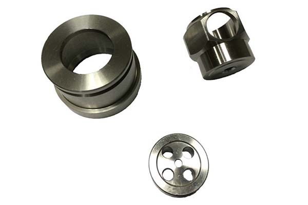
Die casting defects cost manufacturers 5-12% of annual production value . They force rework or scrapping and compromise part performance—especially for safety-critical components like automotive sensors or aerospace brackets. While hot chamber and cold chamber processes have unique defect risks, most issues stem from shared root causes: mold design flaws, parameter mismatches, or material inconsistencies.
What Are the Five Core Categories of Die Casting Defects?
Filling defects
| Defect | Key Characteristics | High-Incidence Areas | Detection |
|---|---|---|---|
| Undercasting | Metal fails to fill cavity; incomplete part shape | End of castings, narrow deep cavities like USB connector slots | Visual inspection; dimensional measurement—part shorter than design |
| Cold separation | Low-temp metal flows meet but don’t fuse; irregular linear gaps may penetrate; often with flow marks or surface bubbles | Thick-thin wall transitions like automotive sensor housings | Visual; ultrasonic testing for hidden gaps |
| Flow marks | First-entering metal forms thin layer; covered by subsequent metal, leaving flow-direction traces; partial sunken feel | Large flat surfaces like laptop hinge bases; near gates | Visual; touch test detects slight depressions |
Surface damage defects
| Defect | Key Characteristics | High-Incidence Areas | Detection |
|---|---|---|---|
| Abrasion (strain) | Surface scars from metal adhesion or insufficient mold draft; severe cases have cracks | Mold release direction like cylindrical part edges | Visual; 10× magnifying glass for fine scars |
| Pockmarks | Small pockmark-like areas; rough surface texture | Caused by low mold or alloy temperature during filling | Visual; surface roughness tester—Ra >6.3μm indicates defects |
| Mesh burrs | Mesh-shaped bulges and metal burrs; caused by mold thermal fatigue | Mold parting surfaces like zinc alloy faucet handles | Visual; edge feel detects sharp burrs |
Abnormal shape defects
| Defect | Key Characteristics | High-Incidence Areas | Detection |
|---|---|---|---|
| Depression (shrinkage) | Concave areas on smooth surfaces; often with dimples | Thick-walled areas or wall thickness transitions like battery terminal bases | Visual; laser scanning measures surface flatness |
| Deformation (warping) | Overall or partial geometry mismatch with design; bent brackets | Thin-walled parts like LED heat sinks; large flat components | Dimensional testing with calipers; CMM |
| Wrong edge (mismatch) | Relative displacement on both sides of parting surface; step-like gaps | Mold split lines like toy car bodies | Visual; feel test detects step differences |
Internal quality defects
| Defect | Key Characteristics | High-Incidence Areas | Detection |
|---|---|---|---|
| Shrinkage & loosening | Holes or loose tissue from solidification contraction; low density | Thick-walled cores like engine block ribs; wall thickness changes | X-ray flaw detection; density testing—lower than material standard |
| Bubbles | Gas accumulation under epidermis; bulging bubbles may penetrate or be closed; easy to crack when stressed | Near mold vents like 3C part inner cavities | X-ray testing; heat treatment—bubbles expand and become visible |
| Cracks | Filamentous gaps; cold cracks—no oxidation, brittle; hot cracks—oxidized edges, ductile | High-stress areas like part corners; after heat treatment | Ultrasonic testing; dye penetrant inspection for surface cracks |
Other defects
| Defect | Key Characteristics | High-Incidence Areas | Detection |
|---|---|---|---|
| Flash (fluff) | Excess metal flakes on edges or splices; thin and brittle | Mold parting surfaces, insert gaps like bathroom hardware joints | Visual; edge trimming removes excess |
| Imprinting | Uneven marks from pusher or insert splicing; circular dents from ejector pins | Pusher contact areas like part bottoms | Visual; touch test detects unevenness |
| Colored spots | Heterochromatic spots—black, brown; caused by paint carbides or punch oil | Surface of decorative parts like zinc alloy toy casings | Visual; solvent wiping tests if spots are removable |
| Layering (clamping) | Obvious metal layers inside part; thick flash on parting surfaces | Caused by multiple metal flow layers not fusing | Sectioning inspection; X-ray testing shows layer boundaries |
What Are the Root Causes Across Three Key Links?
Mold design flaws cause 30-40% of defects
Insufficient draft angle: Draft under 1° for zinc alloys causes metal adhesion, leading to abrasion and deformation.
Poor gate or exhaust design: Small gate size under 1mm for thin parts slows filling, causing undercasting. Blocked exhaust grooves under 0.2mm depth trap gas, leading to bubbles.
Uneven cooling channels: Channel spacing over 20mm creates temperature gradients over 30°C, causing cold separation and shrinkage depressions.
Thermal fatigue: Molds used over 100,000 shots without maintenance develop cracks, leading to mesh burrs and layering.
Process parameter mismatches cause 40-50% of defects
| Defect | Key Parameter Cause | Quantitative Thresholds (Zinc Alloys) |
|---|---|---|
| Undercasting | Low injection pressure/speed; low alloy temperature | Pressure <5MPa; speed <0.5m/s; temperature <380°C |
| Cold separation | Slow filling speed; large temp drop between metal and mold | Speed <0.8m/s; mold temperature <150°C with alloy at 400°C |
| Bubbles | High injection speed causing turbulence; insufficient holding pressure | Speed >2m/s; holding pressure <8MPa |
| Shrinkage depression | Short holding time; low holding pressure | Holding time <5s; pressure <10MPa |
| Deformation | Uneven cooling time; mold opening too early | Cooling time <3s for thin parts; mold opening <2s after solidification |
Material quality issues cause 10-20% of defects
Alloy impurities: Iron content over 1.2% in zinc alloys causes hard particles, leading to pockmarks and cracks.
Moisture or gas content: Hydrogen over 0.3cc/100g in aluminum alloys creates bubbles during solidification.
Oxide slag: Unfiltered molten metal with slag over 0.5% causes layering and shrinkage loosening.
| Root Cause Category | Share | Primary Issues |
|---|---|---|
| Mold design | 30-40% | Draft angle, gate/exhaust, cooling, thermal fatigue |
| Process parameters | 40-50% | Pressure, speed, temperature, holding time |
| Material quality | 10-20% | Impurities, gas content, oxide slag |
How Do You Fix and Prevent Defects Systematically?
Targeted fixes for high-frequency defects
| Defect | Immediate Fix | Long-Term Prevention |
|---|---|---|
| Undercasting | Increase injection pressure by 2-5MPa or speed by 0.2-0.5m/s; raise alloy temperature by 10-15°C | Optimize gate size—gate width = 2× part thickness; clean exhaust grooves weekly |
| Cold separation | Preheat mold to 180-200°C for zinc; increase alloy temperature by 15-20°C; use larger gate | Add diversion ribs at angle ≤10° to guide flow; install mold temperature controllers at ±5°C tolerance |
| Bubbles | Reduce injection speed by 0.3-0.5m/s; extend holding time by 2-3s; add vacuum exhaust at ≥90kPa | Use inert gas protection—argon or nitrogen during melting; filter molten metal with 20-ppi ceramic foam |
| Shrinkage depression | Increase holding pressure by 3-5MPa; extend holding time by 3-5s; add local cooling channels near thick walls | Optimize part design—reduce wall thickness difference to ≤2:1; use risers for thick-walled areas |
| Abrasion (strain) | Polish mold cavity to Ra ≤1.6μm; increase draft angle to 1.5-2°; apply thin uniform release agent | Use wear-resistant mold materials like H13 steel; coat cavity with TiN for zinc alloys |
Mold optimization for defect-resistant designs
Draft angle: Ensure minimum 1° for zinc, 2° for aluminum —prevents abrasion.
Exhaust system: Add exhaust grooves at depth 0.1-0.2mm, width 5-10mm at final filling zones. For complex parts, use vent pins at diameter 0.5-1mm.
Cooling channels: Space channels 15-20mm apart; align with thick-walled areas—5mm from 10mm-thick walls—to reduce temperature gradients.
Gate design: Use fan gates for large flat parts—ensures uniform filling. Use pinpoint gates at diameter 0.8-1.2mm for small 3C components.
Process control to stabilize parameters
Temperature control:
- Alloy: 380-420°C for zinc, 680-720°C for aluminum. Use digital thermostat at ±5°C tolerance.
- Mold: 150-200°C for zinc, 200-250°C for aluminum. Monitor with infrared thermal imagers.
Injection parameters:
- Hot chamber for zinc: Pressure 10-20MPa, speed 0.5-1.5m/s.
- Cold chamber for aluminum: Pressure 30-80MPa, speed 2-5m/s.
Quality checks:
- First-part inspection: Check dimensions, surface, internal quality with X-ray for critical parts at start of each shift.
- Statistical Process Control: Track parameters like temperature and pressure and defect rates. Set control limits at ±10% for pressure.
How to write a spec that gets priced correctly
A drawing is a contract. If it leaves a number open, the shop fills that number in with its own default. The default is rarely the one you had in mind. Put these five lines on every RFQ and most of the back-and-forth disappears before it starts.
- 3D model with the parting line marked
- Alloy grade and the standard it meets
- Wall thickness and draft on every face
- Machining allowance on the faces that will be cut
- Pressure tightness or porosity class
The point is not paperwork. Each line removes a decision the shop would otherwise make for you. A complete RFQ comes back priced. An incomplete one comes back guessed.
What actually drives the price
Buyers usually push on material because it is the line they can see. In practice the material is rarely the biggest number on a quote. These five lines decide most of it:
- die steel and cavity count
- part weight and wall section
- draft and slide count
- porosity requirement
- machining allowance
Ask for the quote split by line. A supplier who cannot break it down is guessing, and you will pay for the guess. The line you can usually renegotiate is the tolerance band, not the raw material.
Problems you will meet, and the fix
Every process has a failure mode it prefers. The same four show up again and again on this kind of work, and none of them are mysteries once you know what to look for.
- Cold shuts where two flow fronts meet
- Porosity that shows up only after machining
- Soldering on a hot spot in the die
- Shrinkage voids in a heavy section
Catch the fault on the first part, not the hundredth. A first-article check costs an hour. A bad batch costs the whole order. Write the check into the purchase order so nobody has to remember it.
What to check on the first article
The first article is the cheapest inspection you will ever buy. Use it properly and the rest of the run becomes boring, which is exactly what you want.
- Every dimension on the drawing, with the measured value written beside it.
- The material certificate, matched to the heat or lot number on the parts.
- The finish against the sample you approved, under the same light.
- Fit against the mating part, assembled rather than measured.
- Packaging, because parts that arrive damaged were never in tolerance.
Check in this order: datums, then mating features, then cosmetic faces. If the datums are wrong, every number after them is noise. Keep the report on file. When a problem shows up in month six, that document is the only thing that tells you what changed.
How to compare two quotes fairly
Two numbers are not comparable unless the scope matches. Line them up before you decide, because a low number with three gaps is not a low number.
Same drawing, same material, same finish, same inspection. Anything else is a different job wearing the same part number. Then look at what each quote leaves out. Freight, packaging, certificates and tooling are the usual gaps.
Ask each supplier to state their assumptions in writing. The one who does is usually the one who has run the process before.
Scaling from one part to a batch
The first part teaches you the process. The hundredth teaches you the process cost.
Watch three things as volume grows: setup amortisation, tool wear, and how much hand work the finish still needs. If the unit price barely moves between ten and a hundred, the cost sits in material or in hand work, not in setup. Ask which, because only one of them is negotiable.
Lead time behaves the same way. A one-off is scheduled around other jobs. A repeat order is scheduled around your forecast. Give the shop a forecast and the lead time gets shorter, not longer.
How to read a supplier's quote
A quote is a short document with a long shadow. Four things in it decide whether the job runs smoothly, and only one of them is the price.
- The scope line. It should name the process, the material and the finish, not just the part.
- The tolerance basis. General tolerance or the drawing, and which standard it follows.
- The exclusions. Tooling, freight, certificates and inspection are the usual omissions.
- The validity date. Material prices move, and an open-ended quote is a promise nobody can keep.
Read the exclusions before you read the total. A quote that leaves out tooling is not cheaper. It is a quote for a different job.
What to send with the first order
The first order sets the pattern for every order after it. Send a complete package once and the shop files it, and the second order takes a fraction of the time.
- A STEP or native model plus a PDF drawing carrying the same revision letter.
- The material callout by standard number, not by trade name.
- The finish and the exact faces it applies to.
- Any test the part must pass: fit, seal, drop, salt spray, dielectric.
- A contact who can answer a question inside one working day.
Then write down what was agreed. An email that confirms the material, the finish and the date is worth more than a longer purchase order that leaves them open.
Industry Experience: Defect Resolution in Action
A zinc alloy faucet handle manufacturer had 12% scrap from mesh burrs and abrasion. Investigation showed mold thermal fatigue after 120,000 shots without maintenance. Solution: TiN coating on cavity and weekly polishing to Ra 1.2μm. Mesh burrs eliminated. Abrasion dropped to under 1%.
An aluminum automotive sensor housing producer faced 8% cold separation defects. Root cause: mold temperature gradient of 40°C —260°C at gate, 220°C at far end. Installing mold temperature controllers with ±5°C tolerance across cavity eliminated gradient. Cold separation dropped to 0.5%.
A 3C electronics manufacturer had 10% bubbles in thin-walled parts. X-ray showed gas entrapment. Fix: vacuum exhaust at 90kPa and 20-ppi ceramic foam filtration. Bubbles reduced to 1%. Heat treatment no longer expanded hidden pores.
Common die casting defects fall into five categories—filling defects like undercasting and cold separation; surface damage like abrasion and pockmarks; abnormal shape like shrinkage depressions and warping; internal quality like bubbles and cracks; and other defects like flash and colored spots. Root causes split across mold design at 30-40%, process parameters at 40-50%, and material quality at 10-20%. Solutions require targeted fixes—increasing pressure for undercasting, preheating molds for cold separation, reducing speed for bubbles, extending hold for shrinkage. Long-term prevention means optimizing mold design with proper draft, exhaust, cooling, and gates; controlling processes with tight temperature and parameter ranges; and maintaining material purity. With systematic approaches, defect rates can drop from double digits to under 2%.
Our solution for Common Die Casting Defects
YiguProto runs die casting in house, from a single prototype to a production batch. We quote the process, the material and the finish as separate lines, so you can see where the money goes instead of arguing with one number.
Send a STEP file or a drawing and you get a DFM report in one to two business days. It flags the features that add cost and the features that will not hold tolerance on the process you picked.
Every order ships with an inspection report on the features you call out. If a part misses, we make it again. Ready to price a part? Start with a free quote and DFM review, or read more about our die casting. You can also talk to an engineer before you commit to a drawing.
FAQ about Common Die Casting Defects
Can Common Die Casting Defects be made in small quantities?
Yes, and small quantities are where a good supplier earns the next order. Setup dominates the price at low volume, so the cheapest route is usually the one with the fewest operations, not the cheapest material.
How much does Common Die Casting Defects cost?
Price comes from five lines: material, machine or tool time, setup, finishing and inspection. The material itself is usually the smallest of them. Send a drawing and we will split the quote so you can see which line is doing the damage.
What material should I specify?
Specify by standard, not by trade name. A trade name can change under you between two orders; a standard number cannot. Then add the one property that actually decides the part, whether that is strength, heat resistance or chemical exposure.
What is Common Die Casting Defects used for?
Common Die Casting Defects turns up wherever the part has to do a real job at a predictable cost: brackets, housings, fixtures, covers and the fittings that hold them together. The honest test is whether the properties match the load and the environment, not whether the material is fashionable.
What is the lead time for Common Die Casting Defects?
Expect 20 to 30 business days including die build. Tooling, material stock and the finishing queue all move that number, so we confirm the date in writing before the run starts rather than after.
What tolerance can you hold on Common Die Casting Defects?
The working default is ±0.1 mm on cast features, ±0.05 mm after machining. Tighter than that the process changes and so does the price, because every step tighter adds inspection time. Call out only the faces that mate with something else and leave the rest on the general tolerance.
The short version
Common Die Casting Defects rewards the buyer who reads the data sheet and the drawing together. Pick the option for the property that matters, not for the price per kilo.
Tighten only what mates. Test a sample before the run. Then let the process do the rest.