
Blogs
Is Gantry Machining Right for Your Large-Scale Production Needs?
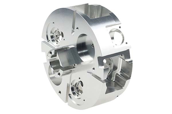
Gantry machining stands as a cornerstone technology in modern manufacturing. When you need to process massive workpieces—think aircraft wings, wind turbine hubs, or heavy machinery beds—standard machining centers simply cannot handle the job. Gantry machining offers the perfect solution with its large working envelope, exceptional rigidity, and high precision.
What Exactly Is Gantry Machining?
Defining the Gantry Structure
Gantry machining refers to a machining process performed on equipment with a distinctive “gantry” frame design. Imagine a bridge supported by two columns—that is essentially the structure. The beam sits atop columns on both sides, creating a rigid frame. The workpiece mounts on a table beneath this frame, while the cutting tool moves across the beam to perform machining operations.
This structural design delivers two massive benefits. First, the closed-frame construction distributes cutting forces evenly, minimizing vibration. Second, the tool moves while the workpiece remains stationary or moves minimally, which proves ideal for heavy, awkwardly shaped parts.
From Manual to CNC Evolution
Traditional gantry milling machines required manual operation. Today, CNC gantry machining centers dominate the industry. These computer-controlled systems automate the entire process, enabling complex multi-axis machining with minimal operator intervention.
Industry data reveals the global CNC gantry machining center market reached $8.6 billion in 2024, growing 7.2% year over year. The aerospace and new energy sectors alone drive over 40% of this demand. This growth reflects manufacturing’s shift toward larger, more complex components requiring tighter tolerances.
How Does a Gantry Machining Center Work?
The Basic Operating Principle
Gantry machining operates on a straightforward principle: precise movement coordination between the tool and workpiece. The spindle holds the cutting tool and rotates at high speed. Meanwhile, servo motors drive the machine axes to position the tool exactly where material needs removal.
The rigid gantry frame absorbs cutting forces, maintaining accuracy even during heavy material removal. Think of it like using a bridge crane—the structure remains stable regardless of where the load moves along the beam.
Step-by-Step Workflow
Workpiece setup begins the process. You secure the part to the worktable using clamps, fixtures, or vacuum systems. Proper alignment proves critical here—positioning errors should stay under 0.02mm to ensure final accuracy.
Program preparation comes next. Using CAD/CAM software, you create toolpaths defining every movement. The software converts these paths into G-code that the machine understands. Modern systems allow simulation before cutting, catching potential collisions or errors.
Parameter input involves setting tool offsets, work coordinates, and cutting conditions. The operator enters tool lengths, diameters, and compensation values into the CNC control.
Machining execution starts when you press the cycle start button. The machine follows the program precisely, moving axes simultaneously to create the desired shape. The CNC system monitors everything in real time, stopping immediately if problems arise.
Final inspection verifies results. Coordinate measuring machines or other precision instruments check critical dimensions. Any deviations prompt program adjustments for subsequent parts.
What Are the Key Components of a Gantry Machine?
Breaking Down the Critical Parts
The table below outlines the essential components that determine gantry machine performance:
| Component | Primary Function | Quality Indicators | Industry Standards |
|---|---|---|---|
| Beam | Supports headstock, enables cross travel | Material strength, cross-section design, stress relief | High-strength cast iron or welded steel, deformation ≤0.02mm/m |
| Columns | Support beam, maintain frame rigidity | Height-to-width ratio, connection accuracy | Verticality error ≤0.015mm/m, rigid base connection |
| Worktable | Holds workpiece, provides longitudinal feed | Size capacity, load rating, guideway type | Load capacity ≥5t/m², positioning accuracy ≤0.01mm |
| Headstock | Houses spindle, enables vertical movement | Spindle power, speed range, rigidity | Speed 50-8000rpm, power ≥15kW, runout ≤0.005mm |
| CNC System | Controls all axis movements | Response speed, programming ease, compatibility | FANUC 31i, Siemens 840D, five-axis capable |
Real-World Component Performance
Consider a heavy machinery manufacturer processing 20-ton machine tool beds. Their double-column gantry mill uses a welded steel beam with two aging treatments. The columns integrate with the base as single castings. This combination maintains accuracy within 0.03mm during heavy cuts—30% better than their previous equipment.
The lesson here? Component quality directly determines machining capability. Investing in well-designed, properly manufactured components pays dividends through better accuracy and longer machine life.
What Types of Gantry Machines Exist?
Fixed Bridge Gantry Mills
Structural design: The beam remains fixed in position on the columns. The worktable moves longitudinally beneath it, while the headstock moves laterally along the beam and vertically up and down.
Best applications: Long, relatively narrow workpieces suit this design perfectly. Machine tool beds, guide rails, and similar components benefit from the simple, rigid construction.
A machine tool builder processes 12-meter-long bed ways on a fixed bridge mill. Width measures just 1.5 meters, but the length demands the machine’s large travel. They achieve H7 tolerance consistently across production runs.
Moving Bridge Gantry Mills
Structural design: Here the beam moves vertically on the columns. The headstock travels laterally along the beam. The worktable may remain stationary or provide longitudinal movement.
Best applications: Complex, variable-height workpieces benefit from this flexibility. Aerospace fuselage frames and large molds change height along their length, requiring the beam adjustment capability.
Industry data shows moving bridge designs account for 65% of aerospace applications. The ability to accommodate varying workpiece heights proves essential for machining structural components.
Moving Table Gantry Mills
Structural design: The gantry remains stationary while the worktable moves longitudinally on the bed. The headstock provides cross and vertical movement along the beam.
Best applications: Extremely heavy workpieces benefit from this configuration. The fixed gantry provides maximum rigidity, while the moving table carries the load.
Shipyards frequently use moving table designs for hull components. One facility processes 30-ton rib sections, achieving 25% higher efficiency than previous methods.
Gantry Machining Centers
Structural design: These machines add automatic tool changers and tool magazines to basic gantry mills. They support milling, drilling, boring, and tapping in single setups.
Best applications: Complex parts requiring multiple operations benefit most. Automotive dies, mold components, and aerospace structural parts often need various tools and processes.
Statistics indicate gantry machining centers reduce complex part cycle times by over 40%. Fewer setups mean less handling time and better accuracy.
Special Configurations
Hybrid gantry mills combine traditional rigidity with high-speed machining capabilities. They suit precision large parts requiring both material removal and fine finishing.
Double-column designs feature symmetrical column construction for maximum rigidity. Ultra-large precision work—turbine components, nuclear parts—demands this configuration.
Where Is Gantry Machining Used?
Aerospace Industry Applications
Critical components: Aircraft wing spars, fuselage frames, engine casings, landing gear structures. These parts share common characteristics—large size, tight tolerances, difficult materials like titanium and aluminum alloys.
Real example: An aerospace manufacturer uses five-axis gantry centers for wing spars measuring 8 meters long. Machining accuracy holds ±0.02mm on these critical structures. Their pass rate exceeds 99.5%.
Market significance: Aerospace consumes roughly 30% of global high-end gantry equipment. Projected growth remains above 8% annually for the next five years.
Automotive Industry Applications
Critical components: Large body panels dies, bumper molds, engine blocks, transmission housings. Gantry machining enables complete die machining in single setups, eliminating mismatch errors.
Real example: An automotive supplier machines 3.5×2.2-meter body panel dies on gantry centers. Surface roughness measures Ra≤0.8μm, extending die life 50% compared to conventional methods.
Shipbuilding Applications
Critical components: Hull ribs, deck sections, engine foundations. These parts combine massive size with weight that challenges conventional equipment.
Key benefits: Gantry machining allows complete processing of large sections, reducing on-site fitting work. Shipyards report 35% better assembly accuracy and 20% faster assembly using gantry-machined components.
Energy Sector Applications
Critical components: Wind turbine hubs, bases, blade molds; nuclear pressure vessels, turbine blades; hydroelectric runners. These parts face extreme service conditions demanding perfect machining.
Real example: A wind turbine manufacturer machines 4.2-meter diameter hubs on double-column gantries. Flange flatness requirements demand exceptional rigidity. Their finished products show 40% better operational stability.
Heavy Machinery and Beyond
Rail transport components, construction equipment parts, large machine tool construction—all rely on gantry machining. The common thread remains size, weight, or complexity exceeding standard machine capabilities.
What Are the Pros and Cons of Gantry Machining?
Major Advantages
Size capacity stands unmatched. Gantry machines handle parts meters long weighing hundreds of tons—impossible on other equipment types.
Rigidity and stability come from the closed-frame design. Cutting vibration amplitudes measure 60% lower than comparable open-side machines. This stability directly improves surface finish and tool life.
Precision capability reaches ±0.01mm positioning on quality machines. High-end systems achieve even tighter tolerances, meeting aerospace and medical requirements.
Heavy cutting capacity allows aggressive material removal. When machining 45 steel, gantry mills remove material 50-80% faster than standard mills.
Versatility and efficiency improve with machining center configurations. Automatic tool changes, multiple operations per setup, and complex surface machining all contribute to productivity.
Labor reduction follows automation. Fewer setups mean less handling. Automatic operation reduces direct labor hours per part.
Potential Drawbacks
Initial investment runs high. Complex structures, precision components, and large size drive purchase costs well above standard machines.
Maintenance expenses continue the theme. Annual costs typically run 3-5% of acquisition price. Guideway reconditioning, spindle repairs, and control upgrades add up.
Operator skill requirements exceed those for conventional machines. New operators need 3-6 months training before independent work. Programming complexity adds another learning curve.
Energy consumption reflects machine size. Large motors, hydraulic systems, and auxiliary equipment draw significant power during operation.
Floor space requirements demand adequate facilities. Machine footprints often exceed 100 square meters, with height clearance needed for full column travel.
How Do You Select the Right Gantry Machine?
Workpiece Specifications Come First
Size matching requires machine travels exceeding your largest part. Industry practice suggests 10-20% extra for clamping allowance and tool clearance.
Weight capacity must accommodate your heaviest workpiece. Table loading specifications indicate maximum distributed and concentrated loads. Exceeding these risks accuracy loss and component damage.
Material considerations influence machine selection. Hard materials like titanium need high power and rigidity. Aluminum and composites may benefit from high-speed spindles.
Processing Requirements Matter
Accuracy needs determine required machine precision. Parts requiring ±0.01mm tolerances need machines with ≤0.008mm positioning capability. Looser requirements allow more economical choices.
Surface finish specifications influence spindle and guideway selection. Fine finishes (Ra≤0.8μm) need high-speed spindles, precision guideways, and quality tooling.
Process variety dictates machining center requirements. Multiple operations favor automatic tool changing. Simple profiling may justify basic mills.
Spindle and Axis Selection
Spindle power should match your material removal needs. Heavy roughing demands ≥22kW continuous rating. Finishing passes need less power but possibly higher speeds.
Spindle speed requirements vary by application. Hard materials need lower speeds with high torque. Aluminum and composites benefit from ≥8000rpm for productive cutting.
Axis count depends on part complexity. Three axes suffice for prismatic parts. Five-axis capability enables complex surfaces in single setups.
Structural Considerations
Frame construction affects long-term accuracy. One-piece castings or welded steel with proper stress relief maintain geometry years longer than lesser designs.
Guideway type influences precision and life. Linear guideways offer superior positioning accuracy and smooth motion. Box ways provide maximum damping for heavy roughing.
Coolant and chip management systems deserve attention. Large machines generate significant heat and chips. Effective systems maintain thermal stability and prevent chip accumulation.
Control System Selection
Brand reputation matters for reliability and support. FANUC, Siemens, and Heidenhain dominate the market for good reason—they work consistently.
Software compatibility ensures efficient programming. Your CAM system must post-process effectively for the chosen control. Verify this before purchase.
Automation and Features
Tool changers add productivity for multi-operation work. Capacities from 24 to over 60 tools accommodate most needs.
Probe systems enable in-process measurement and setup automation. They reduce manual intervention and improve consistency.
Chip conveyors prove essential for production work. They remove swarf automatically, allowing unattended operation.
Facility and Budget Realities
Space requirements must accommodate machine dimensions plus operating clearances. Allow room for workpiece loading, tool setup, and maintenance access.
Total cost evaluation includes purchase price, installation, tooling, training, and operating costs. Return on investment calculations should factor all these elements.
Industry data suggests high-end gantry machining centers typically pay back within 2-3 years for well-utilized machines.
How Do Gantry and Bridge Machining Centers Compare?
Many users confuse these similar-sounding machine types. The table below clarifies key differences:
| Aspect | Gantry Machining Center | Bridge Machining Center |
|---|---|---|
| Structure | Columns at table sides, beam moves on columns | Beam ends supported on bed ways, beam moves along bed |
| Rigidity | Higher, better for heavy cuts and large parts | Moderate, suited for medium precision work |
| Work Envelope | Larger, accommodates bigger workpieces | Smaller, limited by bridge structure |
| Applications | Aerospace, heavy machinery, large dies | Moldmaking, precision components, smaller parts |
| Cost | Higher investment and maintenance | More economical for suitable work |
How to write a spec that gets priced correctly
A drawing is a contract. If it leaves a number open, the shop fills that number in with its own default. The default is rarely the one you had in mind. Put these five lines on every RFQ and most of the back-and-forth disappears before it starts.
- A model and a drawing that agree
- Material by standard number
- Tolerance only where it mates
- Finish and the faces it applies to
- Quantity and required date
The point is not paperwork. Each line removes a decision the shop would otherwise make for you. A complete RFQ comes back priced. An incomplete one comes back guessed.
What Do Industry Experts Recommend?
Practical Selection Advice
Match the machine to your work, not the other way around. Define your part family clearly before evaluating equipment. List current and anticipated future requirements.
Visit operating installations when possible. See machines running your type of work. Talk to maintenance personnel about reliability and service.
Consider the total package—training, support, spare parts availability. The best machine proves worthless without adequate support.
Future Trends
Intelligent features increasingly appear on new machines. Adaptive control, predictive maintenance, and remote monitoring capabilities expand rapidly.
Digital twin integration allows complete process simulation before metal cutting. This reduces prove-out time and eliminates costly errors.
Hybrid manufacturing combines additive and subtractive processes in single machines. This emerging trend may reshape large-part production.
Our solution for Gantry Machining
YiguProto runs custom manufacturing in house, from a single prototype to a production batch. We quote the process, the material and the finish as separate lines, so you can see where the money goes instead of arguing with one number.
Send a STEP file or a drawing and you get a DFM report in one to two business days. It flags the features that add cost and the features that will not hold tolerance on the process you picked.
Every order ships with an inspection report on the features you call out. If a part misses, we make it again. Ready to price a part? Start with a free quote and DFM review, or read more about our custom manufacturing. You can also talk to an engineer before you commit to a drawing.
FAQ about Gantry Machining
What tolerance can you hold on Gantry Machining?
The working default is ±0.1 mm as a working default. Tighter than that the process changes and so does the price, because every step tighter adds inspection time. Call out only the faces that mate with something else and leave the rest on the general tolerance.
How do I compare two quotes fairly?
Match the scope first: same drawing, same material, same finish, same inspection. Then read the exclusions. Freight, tooling and certificates are the usual gaps, and a low number with three gaps is not a low number.
What happens if a part is out of specification?
We measure it against the same drawing you approved and, if it misses, we make it again. What matters is that the report exists, because a disagreement without data is just an opinion.
Is there a minimum order quantity?
No hard minimum. One part is fine. What changes with volume is which costs dominate, so a single unit is priced mostly on setup and a thousand units are priced mostly on cycle time and material.
What is Gantry Machining used for?
Gantry Machining turns up wherever the part has to do a real job at a predictable cost: brackets, housings, fixtures, covers and the fittings that hold them together. The honest test is whether the properties match the load and the environment, not whether the material is fashionable.
Does the process work for prototypes as well as production?
Yes, and that is usually the point. Running the prototype on the production process removes a whole class of surprises, because the part you test is made the same way as the part you sell.
The short version
Gantry Machining rewards the buyer who reads the data sheet and the drawing together. Pick the option for the property that matters, not for the price per kilo.
Tighten only what mates. Test a sample before the run. Then let the process do the rest.